
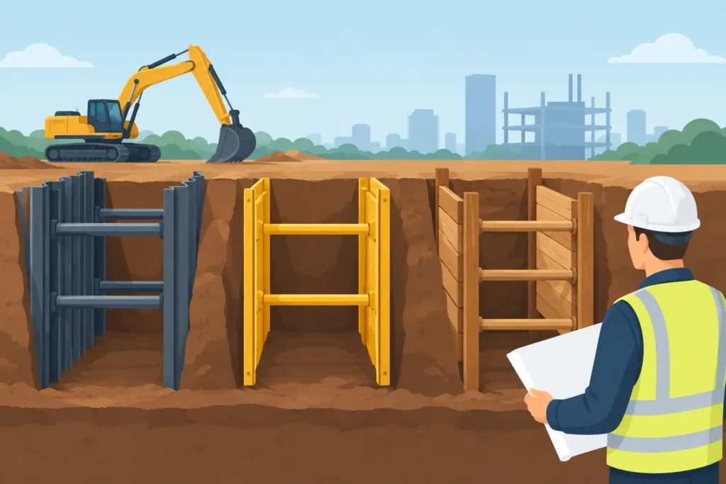
A retaining system that appears economical on a plan drawing can become the most expensive choice once groundwater control, restricted access, adjacent structures and programme risk are considered. A useful excavation support comparison therefore starts with ground behaviour and construction sequence, not with a preferred wall type. The question is not simply which system can retain the soil. It is which system can do so with movements, water inflows and temporary works risk kept within acceptable limits.
For basements, stations, shafts, cut-and-cover tunnels and utility structures, support selection is an interaction between soil, structure and method. The design must account for the fact that support is installed progressively, loads are mobilised progressively, and the retained ground may be highly variable over short distances.
What an excavation support comparison must test
The principal support options – sheet pile walls, soldier pile and lagging walls, contiguous or secant piled walls, diaphragm walls, and soil-nailed slopes – do not provide equivalent performance. Comparing their nominal bending capacity alone is misleading. Wall stiffness, continuity, toe restraint, embedment, groundwater conditions and the support arrangement often govern the outcome more directly.
A practical comparison should assess four linked matters: deformation control, groundwater control, constructability and whole-life project risk. Cost remains essential, but it needs to include enabling works, dewatering, spoil handling, traffic or rail possessions, monitoring and potential protection measures for neighbouring assets.
The soil model also deserves scrutiny. A drained strength approach may be suitable for a long-term granular condition, while short-term excavation in saturated clay may be governed by undrained response. Effective stress changes caused by drawdown can induce settlement well beyond the excavation line. This is one reason a wall that is adequate in a limit-state calculation may still be unsuitable beside sensitive buildings or buried services.
Comparing common excavation support systems
Sheet pile walls
Steel sheet piles are often an efficient solution for temporary excavations in granular soils, soft clays and waterfront works. Installation is rapid where vibration is acceptable, and the interlocking section can provide a useful cut-off against groundwater. The wall can also be extracted and reused in favourable conditions.
Their limitations are equally familiar. Driving can generate vibration and noise, refusal may occur in dense till, bouldery soils or shallow rock, and interlocks should not be treated as perfectly watertight. In urban work, the risk of movement or damage during installation can outweigh the apparent speed advantage. A sheet pile wall may be well suited to an open site but inappropriate beside old masonry, rail infrastructure or vibration-sensitive equipment.
Soldier piles with lagging
Soldier pile and lagging systems are adaptable, particularly where geometry changes or access is constrained. The primary piles can be drilled rather than driven, reducing vibration, and lagging can be installed as excavation proceeds. This makes the method practical for relatively dry, self-supporting soils and for temporary cuttings where modest movement is acceptable.
The discontinuous face is its defining limitation. Timber, precast concrete or sprayed concrete lagging does not form an effective water barrier, and fines can migrate through gaps if the ground is loose or seepage is present. In soft clay or running sand, face stability between piles can be difficult to maintain. It is usually a poor choice where groundwater exclusion or strict settlement control is required.
Contiguous and secant piled walls
A contiguous piled wall consists of closely spaced bored piles, normally leaving small gaps between them. It offers better stiffness and installation control than many open support systems, with relatively low vibration. It is commonly used for urban basements where a drilled solution is preferable.
A secant pile wall overlaps primary and secondary piles to create a more continuous barrier. Compared with contiguous piles, it offers improved groundwater cut-off and reduced soil loss, although actual water tightness depends on pile verticality, overlap, concrete quality and the ground itself. It is not a substitute for a considered water management strategy, especially under substantial hydraulic head.
Both systems require careful tolerances. Small deviations in pile position or inclination can affect overlap, reinforcement placement and final wall geometry. Where wall deflection is critical, the designer must consider the stiffness of individual piles, joints between piles, capping beam behaviour and the support levels. A nominally thick wall can still perform poorly if excavation proceeds beyond the assumed stage before struts, anchors or slabs are engaged.
Diaphragm walls
Diaphragm walls are generally selected when high stiffness, depth and groundwater control are needed. They are particularly relevant for deep excavations near major structures, below the water table, or where the permanent basement wall can be integrated with the temporary works. Properly executed panels can limit ground movements more effectively than less continuous alternatives.
This performance comes with higher mobilisation demands. Guide walls, slurry management, reinforcement cages, concrete supply, panel joint treatment and stringent quality control are integral to the method. The equipment footprint and cost can be difficult to justify for a small excavation. Yet on a deep, high-consequence project, the higher initial cost may be preferable to the uncertainty associated with extensive dewatering or a more flexible support wall.
Soil nailing and reinforced slopes
Soil nailing stabilises the ground mass rather than creating a near-vertical retaining wall. It can be economical for cut slopes and widened corridors where enough space exists for a battered face. Installation in stages aligns naturally with excavation, and sprayed concrete facing can provide local surface restraint and erosion protection.
The method relies on suitable ground conditions. Nails need sufficient bond length and a stable soil mass behind the potential slip surface. Water-bearing granular soils, soft organic deposits and highly variable fill can make performance uncertain. Soil nailing is also not the default answer where land-take is limited or a vertical basement boundary is required.
Wall type is only half of the comparison
The internal support method can change the preferred wall system. Ground anchors leave the excavation clear and can reduce bending moments, but they require rights beyond the site boundary and may be prohibited near tunnels, utilities or neighbouring foundations. They also introduce testing, corrosion protection and long-term responsibility where anchors remain permanent.
Struts avoid off-site anchorages but obstruct excavation, plant movements and permanent works construction. Their load path through waling beams and connection details must be explicit. For wide excavations, the practical difficulty of installing and removing multiple strut levels can be substantial.
Top-down construction can use permanent slabs as horizontal support, often reducing wall movements and avoiding long-term anchors. It can be advantageous in dense urban areas, but sequencing becomes more demanding. Openings for excavation, ventilation, spoil removal and plant access need to be designed as part of the construction method rather than treated as later site arrangements.
Groundwater changes the decision
Groundwater is often the factor that separates a viable concept from a problematic one. A drained excavation may require sump pumping, wellpoints, deep wells, a cut-off wall, base grouting, or some combination. Each approach affects pore pressures differently.
External drawdown can cause consolidation settlement in compressible soils and may alter conditions beneath neighbouring foundations. Conversely, retaining high water pressure outside a deep wall raises demands on wall embedment, base stability and internal drainage. The risk of hydraulic uplift, piping or base heave should be checked for the actual construction stages, not only the completed structure.
For excavations in fractured rock, water inflow is controlled by discontinuities rather than a uniform permeability value. Probe drilling, packer testing and a grouting strategy may be more informative than broad assumptions about rock mass quality. This is particularly relevant for shafts and underground connections where local features govern both inflow and support requirements.
Use calculations to compare behaviour, not merely capacity
Limit equilibrium checks remain valuable for global stability, basal heave, uplift and anchor capacity. They should be complemented, where appropriate, by staged numerical analysis or other deformation-focused methods. The purpose is to estimate how the system mobilises, not to produce a deceptively precise displacement contour.
Input selection should be transparent. Retained height, surcharge, water levels, stiffness parameters, interface behaviour, construction stages and support preloads all need to reflect the proposed method. Sensitivity checks are often more useful than a single refined calculation because they show which uncertainty matters most. In soft clay, for example, the assumed undrained shear strength profile and support installation timing may dominate the result.
Simple, traceable calculation tools are valuable during option development. They allow the engineer to test changes in excavation depth, prop level, anchor inclination or groundwater level quickly, then document the basis for selecting a more detailed model. For engineers working across office and site, software that presents inputs and results clearly on macOS and iOS can help keep these comparisons accessible during design reviews and construction discussions.
Monitoring is part of the design method
Monitoring should not be added only to satisfy a specification. In an observational approach, it provides the evidence needed to confirm whether the ground and support are behaving within the expected range. Inclinometers, settlement points, piezometers, strut load cells and survey targets should be selected according to the failure modes and performance criteria that matter.
Trigger levels need a defined response. If wall movement exceeds an alert threshold, the team should know whether to pause excavation, install the next support level, alter dewatering, reduce surcharge or investigate instrumentation. Data without agreed actions does not manage risk.
The best support system is therefore rarely the strongest wall in isolation. It is the system whose installation, groundwater behaviour, calculated movements and monitoring plan are credible for the ground and constraints of the particular excavation. A disciplined comparison at concept stage gives the project team room to choose that system before temporary works become an emergency decision.
