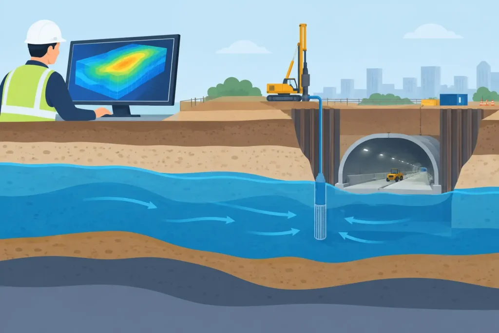
A tunnel face that appears dry at chainage 120 can still be connected to a permeable fracture zone, a pressurised sand layer or a distant recharge boundary. The engineering consequence may only become visible when excavation, pumping or grouting changes the hydraulic regime. Groundwater modelling provides a structured way to test those connections before they become a programme, safety or claims issue.
For geotechnical and tunnelling engineers, the purpose is not to produce an impressive colour plot. It is to develop a model that is simple enough to interrogate, technically defensible, and sufficiently detailed for the decision at hand. The required model for a temporary excavation is not necessarily the required model for a long railway tunnel beneath sensitive buildings.
What groundwater modelling is intended to answer
At its core, a groundwater model represents the relationship between geology, hydraulic properties, recharge, boundaries and engineered interventions. It estimates groundwater heads, flow directions, seepage quantities and, where needed, changes over time.
The questions should be set before the model is built. For an excavation, the key question may be whether drawdown will extend beyond the site boundary and cause settlement in compressible soils. For a tunnel, attention may turn to inflow at the face, the pore pressure acting on a lining, or the likely effectiveness of pre-grouting. For a dam foundation or hydropower tunnel, the central issue may be seepage paths through rock mass discontinuities and the residual pressures after treatment.
These are different problems. A model should therefore be selected and configured to answer a defined engineering question, rather than becoming a general digital representation of the ground.
Conceptual model first, numerical model second
The most consequential part of the work often happens before numerical calculation begins. The conceptual groundwater model sets out the hydrostratigraphy, groundwater units, likely flow paths, recharge and discharge mechanisms, and the features that control connectivity.
In soil, the relevant layers may include fill, clay, sand and glacial deposits, with particular attention to thin but continuous permeable horizons. In rock, the matrix permeability may be negligible while faults, fracture zones, joints and contact zones govern flow. Treating a fractured rock mass as a uniform porous medium can be appropriate for some regional assessments, but it may conceal the local pathways that matter at a tunnel heading.
The conceptual model should also identify boundaries. A lake, river, coast, drainage tunnel, pumping well or nearby basement excavation may be hydraulically significant. So may a supposed boundary that is not actually closed. Groundwater systems rarely respect project limits.
Choosing the right level of detail
There is no universal answer to how detailed a groundwater model should be. The appropriate level depends on the consequence of being wrong, the available data and the decision that needs support.
A preliminary feasibility assessment may use water balance calculations, observed groundwater contours and analytical estimates of inflow. These methods are fast and transparent. They can identify whether a scheme is likely to need extensive dewatering, a cut-off wall or a grouting programme.
A numerical groundwater model becomes more useful where geometry is complex, multiple aquifers interact, transient effects matter, or the consequences extend beyond the immediate works. Typical examples include staged excavation in urban ground, tunnel construction beneath groundwater-dependent assets, and grouting in variable rock conditions.
More detail is not automatically better. Fine grid spacing, numerous layers and highly local parameter zones can create an appearance of certainty that the investigation data cannot support. Every additional degree of freedom must be justified by evidence or by a clear hypothesis being tested.
Steady-state and transient conditions
A steady-state model assumes that heads and flows are not changing with time. It can be suitable for understanding long-term average conditions or establishing an initial condition. It is often a useful first step, particularly where monitoring records are limited.
Construction rarely occurs under steady-state conditions. Dewatering rates change, rainfall varies, grouting alters conductivity, tunnel advance exposes new ground, and recharge may be seasonal. A transient model is required when the timing and duration of drawdown, recovery or inflow are material to the design.
The trade-off is data demand. Transient calibration requires groundwater levels and, ideally, flow records over a period that captures the relevant variations. If those records do not exist, it is better to state the limitation clearly and test a range of plausible responses than to present a single precise forecast.
Data quality controls the value of the result
Hydraulic conductivity values are frequently the weakest link. Laboratory tests may not represent field-scale fractures, fissures or heterogeneity. Pumping tests can provide valuable integrated information, but their interpretation depends on test duration, observation well response, boundary effects and well losses. Packer tests in rock are informative at the tested interval, yet may not describe connectivity between intervals.
This does not mean that modelling must wait for perfect information. It means the inputs should retain their engineering meaning. Parameter ranges should reflect the investigation, geological understanding and construction experience, rather than being reduced prematurely to one preferred value.
Calibration should use more than a visual comparison between measured and calculated heads. The modeller should examine whether the model reproduces the hydraulic gradient, seasonal behaviour where relevant, pumping response and observed discharge locations. A good match at a few monitoring points can still be misleading if the model obtains it through unrealistic recharge or boundary assumptions.
For underground works, construction observations are particularly valuable. Probe-hole water losses, tunnel inflows, grouting takes, packer test results and face mapping can progressively improve the model. This is one reason groundwater assessment should be treated as a live engineering process, not a report issued once at design stage.
Groundwater modelling in tunnelling and grouting
Tunnel inflow prediction is often framed as a question of litres per minute. That figure matters for pumping capacity and water treatment, but it is not the whole issue. The spatial distribution of inflow can be more important than the total. A concentrated inflow through a fracture zone may affect face stability, increase erosion risk and require immediate action even when total tunnel inflow remains moderate.
Grouting introduces another level of complexity. The aim may be to reduce inflow, limit drawdown, control pore pressure or improve local ground conditions. A model can test how a reduced-conductivity zone around the excavation influences these outcomes. However, the actual performance of a grout curtain depends on penetration, aperture distribution, grout mix, pressure, refusal criteria and the continuity of untreated pathways.
It is therefore prudent to model grouting as scenarios rather than as a guaranteed impermeable barrier. A base case, an effective treatment case and a less effective case usually provide a more useful basis for risk management. The same principle applies to assumptions about fault conductivity and hydraulic connection to surface water.
Presenting results for engineering decisions
The output should make the decision easier, not transfer the burden to the reader. Maps of calculated head, drawdown contours, inflow plots and water balances are useful when they are linked to defined thresholds. For example, a predicted drawdown contour can be compared with settlement-sensitive assets, consent limits or monitoring trigger levels.
Scenario results should distinguish between uncertainty in the ground and uncertainty introduced by design choices. The first may concern the permeability of a fracture zone. The second may concern whether dewatering is continuous, intermittent or replaced by a cut-off solution. Keeping those uncertainties separate helps project teams decide what to investigate next and what to control during construction.
Clear input handling and traceable assumptions are equally important for calculation tools used across office and site. Engineers working between a Mac workstation, iPad and iPhone need to review the same parameters, observations and results without creating parallel versions of the project. This practical focus on accessible technical work is central to the type of specialised engineering tools developed by Psicons AB.
A model should guide monitoring, not replace it
The most useful groundwater model identifies what to monitor and why. If a predicted drawdown cone reaches a particular clay layer, piezometers should be placed to confirm the response in that layer, not merely in the nearest convenient standpipe. If a fracture zone is expected to control tunnel inflow, flow measurement and face observations should be planned around its anticipated position.
Trigger-action-response plans can then connect predicted behaviour with site control. A rising inflow, a faster-than-predicted drawdown rate or an unexpected head response need defined escalation routes. Monitoring becomes a method of testing the model while there is still time to adjust pumping, sequencing, support or grouting.
A groundwater model earns its place when it makes uncertainty visible, identifies the observations that matter, and supports timely engineering judgement. Used in that way, it is not a substitute for site knowledge. It is a disciplined framework for applying it.