
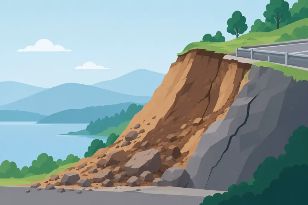
A shallow slip beside a new road cutting can begin with nothing more dramatic than several days of rain. A much larger landslide may develop after years of gradual stress change, erosion and deformation. In both cases, the central question is the same: why do slopes fail when the ground appeared stable before?
The useful engineering answer is not simply that the soil was weak, or that rainfall was heavy. Slope failure occurs when the forces driving movement exceed the shear resistance available along a potential failure surface. The difficulty lies in establishing where that surface may form, which material parameters are relevant, how groundwater behaves, and whether construction or natural processes have changed the balance.
For practising engineers, slope stability is therefore not a single-factor calculation. It is a ground model, a loading history and a drainage problem considered together.
Why Do Slopes Fail? A Balance of Forces
Every slope is subject to gravity. The component of the soil or rock mass weight acting downslope creates shear stress. Resistance comes primarily from effective stress, friction, cohesion where applicable, reinforcement, and the geometry of the slope itself. A stable slope has an adequate margin between resistance and driving force. When that margin reduces below an acceptable level, movement becomes possible.
In limit equilibrium terms, this is commonly expressed through a factor of safety. Yet a satisfactory calculated factor is not a guarantee of performance. It depends on the assumed stratigraphy, pore-water pressures, shear strength parameters, loading conditions and selected failure mechanism. An elegant calculation based on an incomplete geological interpretation can be less useful than a simple calculation supported by good site investigation and observations.
The failure mechanism also matters. A homogeneous clay slope may be assessed using a circular slip surface. Layered soils, weak seams, weathered rock contacts and retaining structures can produce non-circular or composite mechanisms. In rock slopes, planar sliding, wedge failure, toppling and rockfall may govern rather than an overall rotational failure.
Groundwater Is Often the Decisive Variable
Water is one of the most frequent reasons that a previously stable slope becomes unstable. It does not need to create visible flooding to be critical. Rising pore-water pressure reduces effective normal stress, and therefore reduces frictional resistance along a potential slip surface.
This distinction is fundamental. Total stress may remain largely unchanged after rainfall, but if pore pressure rises, the effective stress that mobilises shear strength falls. A slope can then fail without any increase in external load.
The engineering challenge is that groundwater rarely behaves as a simple horizontal water table. Perched water can form above low-permeability layers. Seepage may be concentrated in fissures, old drainage trenches, granular lenses or weathered rock zones. Artesian pressure may develop beneath a confining layer. Seasonal variation, snowmelt, leaking utilities and changes to surface water management can all alter the pore-pressure regime.
Short-duration rainfall may trigger shallow failures in permeable near-surface soils. Prolonged wet periods can affect deeper slip surfaces by allowing water to infiltrate and pressures to build within less permeable strata. Conversely, rapid drawdown adjacent to a reservoir, canal or excavation may remove external water support faster than pore pressures dissipate within the slope.
A groundwater assumption should therefore be traceable to piezometer readings, site observations, hydraulic reasoning and a clearly defined design scenario. Treating groundwater as a secondary input is a common route to misleading stability results.
Geometry, Excavation and Added Loads
Slope geometry determines both the magnitude and distribution of driving forces. Steepening a slope, raising its crest or cutting into its toe changes the stress field. These actions are often undertaken for understandable project reasons, but each can reduce stability.
Excavation at the toe is particularly significant because it removes support where stabilising forces may be most valuable. Road widening, drainage works, utility installation and temporary construction access can all have this effect. If the excavation exposes a weaker stratum or intercepts a seepage path, the consequence may be greater than indicated by the change in geometry alone.
Loading at the crest works in the opposite direction by increasing driving moments. Fill placement, buildings, stockpiles, construction plant and traffic loads require consideration at their actual position and duration. A modest surcharge near the crest can be more influential than a larger load set well back from the slope edge.
Construction sequencing is equally relevant. A final arrangement may meet the required factor of safety while a temporary excavation stage does not. Temporary works deserve the same disciplined ground model and load assessment as permanent works, especially where groundwater response is uncertain or monitoring opportunities are limited.
Soil and Rock Strength Are Not Fixed Numbers
Shear strength parameters are often presented as a cohesion intercept and friction angle, but the values used in analysis must reflect the material, drainage condition and likely mode of failure. A laboratory result is not automatically a design parameter.
For clay slopes, the relevant condition may be undrained during rapid loading, or drained under long-term conditions. Overconsolidation, fissuring, desiccation cracks and strain softening can change the available strength substantially. Where a slope has previously moved, residual strength along an existing shear surface may govern. Using peak strength in that case can produce an unrealistically favourable result.
In granular soils, friction angle is sensitive to density, particle shape, grading and confinement. Loose saturated sand may also require assessment for cyclic loading or liquefaction where seismic actions are relevant. Fill materials can be especially variable, with local changes in composition, compaction and drainage behaviour.
Rock slopes introduce different uncertainties. Discontinuity orientation, persistence, roughness, infilling, water pressure and weathering often control stability more directly than intact rock strength. A strong rock core does not rule out sliding along a weak clay-filled joint.
Parameter selection should make the uncertainty visible. Characteristic values, sensitivity checks and observational evidence are usually more defensible than presenting a single parameter set as certain.
Triggers Often Act on a Pre-Existing Weakness
Many slope failures are described by their immediate trigger: intense rain, a cut at the toe, a leaking pipe or an overloaded crest. This is useful, but incomplete. The trigger usually acts on a slope that already has a susceptible geometry, weak layer, adverse groundwater regime or history of deformation.
A rainfall event may reveal poor drainage rather than being the sole cause. A temporary excavation may activate movement along a pre-existing shear zone. Erosion in a watercourse may remove support from a slope that was already close to limiting equilibrium. This distinction matters because repair measures should address the governing mechanism, not only the event that exposed it.
For example, reprofiling may reduce driving forces effectively where geometry is the main issue. It may be inadequate if high pore pressures remain trapped beneath a low-permeability layer. Installing drainage may be highly effective in one setting and disappointing in another if the drains do not intercept the actual seepage paths.
Recognising Warning Signs Before Failure
Slope movement is not always sudden. Tension cracks near the crest, bulging at the toe, tilting trees or fencing, cracked pavements, distorted drains and new seepage zones may indicate progressive deformation. In engineered slopes, damage to facing systems, displaced blocks or changes in instrument readings can provide earlier evidence.
These signs should prompt inspection by a competent geotechnical professional, particularly after prolonged rainfall, excavation or changes in drainage. They should not be interpreted in isolation. A crack may be caused by shrinkage, settlement or movement, but its position, orientation and development over time can be highly informative.
Monitoring has greatest value when linked to decisions. Piezometers, inclinometers, survey points and remote measurements can clarify the behaviour of a slope, but only if trigger levels, reading frequency and response actions are defined. Data without a conceptual model can create false confidence as easily as no data.
A Defensible Slope Stability Assessment
A practical assessment begins with site reconnaissance and a review of the slope history. Old maps, aerial imagery, maintenance records, previous ground investigations and local accounts may reveal former landslides, filled ground, changed watercourses or earlier remedial works. Ground that has moved before deserves particular attention.
The investigation should then test the assumptions that matter to the likely failure mechanism. This may include boreholes, trial pits, logging of rock discontinuities, laboratory testing, in situ testing and groundwater monitoring. There is no universal investigation layout. A shallow embankment in cohesive fill and a rock cutting above transport infrastructure demand different evidence.
The analysis method should fit the problem. Limit equilibrium methods remain practical and transparent for many soil slopes, provided that slip surfaces, pore pressures and strength assumptions are selected with care. Numerical modelling can be valuable where staged construction, stress redistribution, reinforcement interaction or complex groundwater conditions are central. It also introduces additional modelling choices that must be justified.
Sensitivity analysis is particularly useful. Test credible changes in groundwater level, weak-layer strength, surcharge position and geometry. If a small alteration reverses the result, the design should not be treated as settled. It may require better information, a more conservative intervention or an observational approach supported by monitoring.
Clear calculation tools help keep assumptions visible. Psicons AB develops geotechnical software for macOS and iOS with straightforward input handling, allowing engineers to review slope geometry, loads and results across their working devices. The software does not replace engineering judgement; it supports a disciplined workflow in which the model remains easy to inspect.
Designing Measures That Match the Mechanism
Effective stabilisation follows from the diagnosed cause. Drainage can lower pore pressures through surface control, toe drains, horizontal drains, wells or other arrangements suited to the hydrogeology. Regrading reduces slope angle and driving forces. Berms or buttresses add stabilising weight at the toe. Retaining structures, soil nails, anchors, piles and reinforcement may be appropriate where space is restricted or geometry cannot be altered.
Each measure has trade-offs. Drains require maintainable outlets and may lose effectiveness through clogging or damage. A buttress needs competent foundation conditions and sufficient footprint. Anchors can be efficient but demand careful verification of bond zones, corrosion protection and long-term performance. Hard retaining solutions may transfer loads or groundwater pressures to adjacent ground rather than removing the underlying problem.
The best intervention is often the one that reduces uncertainty as well as increasing calculated stability. A modest change to drainage and slope geometry, verified by monitoring, can be more reliable than a complex structural solution based on poorly constrained pore pressures.
A slope rarely fails for one neat reason. Good geotechnical work identifies the interacting causes, tests the assumptions that control the outcome, and keeps the ground behaviour under review long after the calculation is complete.
