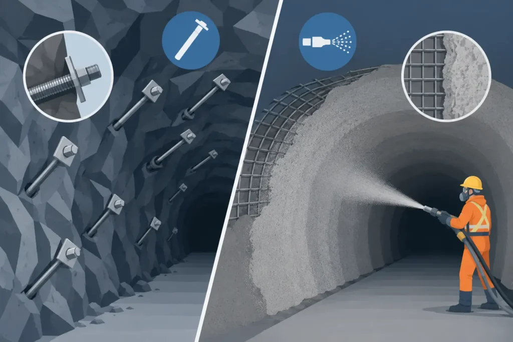
A freshly exposed tunnel face can look competent while carrying discontinuities that will loosen as stress redistributes. That is why rock bolts versus shotcrete support is rarely a simple material choice. The relevant question is how each measure changes the behaviour of the rock mass, and whether the support is installed early enough to control that behaviour.
For tunnel designers and site engineers, bolts and shotcrete should normally be considered parts of one support system. They have different load paths, installation constraints and failure modes. Used with a realistic ground model, systematic mapping and observation during excavation, they can provide efficient support without imposing unnecessary stiffness or cost.
Rock bolts versus shotcrete support: different mechanisms
Rock bolts are reinforcement. Installed across joints, bedding planes, shears or loosened zones, they improve the interaction between blocks and the surrounding rock mass. A fully grouted bolt may transfer load along its bonded length, while a mechanically anchored or friction bolt can provide immediate restraint where that is needed. Cable bolts extend the same principle into larger spans or deeper potential failure zones.
The main benefit is not simply the tensile capacity stated on a data sheet. A bolt is effective only when it intercepts a meaningful failure mechanism and has sufficient anchorage beyond it. In jointed rock, this may mean stitching blocks into a beam or arching zone. In laminated ground, it may restrain separation between layers. In stress-affected ground, the purpose may be to maintain confinement and limit progressive loosening near the excavation boundary.
Shotcrete works primarily as surface support. It prevents ravelling, retains small wedges and fractured material, bridges local irregularities, and helps preserve confinement at the excavation perimeter. Fibre-reinforced shotcrete is particularly useful because its post-crack capacity can accommodate local deformation and redistribute stresses after cracking. Mesh, lattice girders and additional reinforcement may be introduced where specified capacity, span control or construction conditions require them.
A shotcrete lining cannot reliably stabilise a large, detached block without an appropriate connection to stable ground. Conversely, bolts do not stop fine-scale ravelling between bolt heads, nor do they provide continuous face protection in highly fractured rock. The distinction matters when reviewing support classes: bolts control the rock mass internally, while shotcrete controls the excavation surface and ties the near-surface zone together.
Ground conditions govern the balance
In competent, blocky rock with well-defined joint sets, systematic or pattern bolting can be the principal measure. The bolt orientation, spacing and length should reflect the expected wedge geometry, not merely a standard grid inherited from another drive. A thin layer of shotcrete may still be justified to contain small fragments, improve safety at the face and protect weather-sensitive surfaces.
Where rock is highly fractured, altered or crushed, shotcrete often becomes more significant. Early application creates a skin that limits ravelling while bolts provide deeper reinforcement. The support must be applied close to the face because stand-up time, rather than nominal rock strength, may control the risk. Delayed shotcrete in poor ground can allow deformation and damage to develop before the lining begins to participate.
In squeezing or stress-sensitive ground, the preferred balance is less obvious. Stiff, thick shotcrete applied too early may crack as convergence develops. Yet insufficient surface support can allow deterioration and loss of confinement. Yielding bolts, ductile fibre-reinforced shotcrete, staged layers and a carefully selected closure distance may offer a more suitable response. The design needs to consider permitted deformation, not just resistance at installation.
Water changes both construction and performance. Seepage can wash fines from discontinuities, reduce bond quality for grouted bolts and complicate shotcrete adhesion. Drainage holes, water control measures and substrate preparation may therefore be as important as increasing bolt density or shotcrete thickness. A support specification that ignores water is commonly difficult to execute consistently underground.
Classification is a starting point, not a design
Rock mass classifications can help establish an initial support class and provide a common language between design and construction teams. They are valuable at tender and early design stage, particularly when combined with experience from comparable geology. They should not replace structural assessment of wedges, kinematic analysis, numerical modelling where warranted, or face-by-face geological judgement.
The same classification value can conceal very different conditions. A jointed granitic tunnel with persistent wedges behaves differently from a foliated, weathered rock mass with water-bearing seams, even when a rating system places them in a similar range. Support selection should therefore record the observations that led to it: joint persistence, aperture, infill, orientation, groundwater, overbreak, deformation and face stability.
Installation sequence is part of the support design
Bolts and shotcrete may have suitable capacities on paper but perform poorly when installed in the wrong sequence. In a drill-and-blast tunnel, scaling quality is the first practical control. Loose material left behind shotcrete creates voids and weak interfaces; over-scaling may also enlarge the span and disturb the perimeter more than intended.
After excavation, the time to first support should match the observed stand-up behaviour. Some headings benefit from immediate thin flash coat shotcrete before systematic bolting. Others permit bolting first, followed by shotcrete once the bolt heads and plates are in place. The correct sequence depends on ground condition, access, drilling method and the need to keep the face safe during each operation.
Shotcrete thickness must be checked against the actual excavation profile, not only against theoretical contour. Local thin areas at ribs, crown irregularities and around bolt plates can govern performance. Rebound, substrate cleanliness, nozzle distance, air pressure and curing conditions affect the placed material. For fibre-reinforced shotcrete, fibre dosage alone is not proof of structural performance; testing and spraying quality remain essential.
For grouted bolts, borehole cleaning, grout mix, installation time and pull-out verification deserve equal attention. A long bolt with incomplete grout continuity may create more confidence than capacity. Installation records should make it possible to identify bolt type, length, orientation, grout use and location, rather than treating the support pattern as a generic construction activity.
Design the system, then verify it underground
The design process should begin with credible failure modes. Is the concern a shallow wedge, local ravelling, face instability, stress-induced spalling, deep-seated movement or convergence in deformable ground? Each mechanism suggests a different contribution from bolts, shotcrete and, where necessary, girders, forepoling, spiles or a final lining.
The next step is to define design assumptions clearly. These include excavation span and shape, support installation distance from the face, rock mass parameters, discontinuity geometry, groundwater conditions and acceptable deformation. A calculation is only as useful as its assumptions are visible. Simple tools that make input handling and result review straightforward can be particularly valuable when support decisions need to be checked between the office and the heading.
Verification should continue after installation. Convergence pins, extensometers, bolt load cells, shotcrete thickness checks and systematic face mapping provide different evidence about whether the support concept is working. Monitoring is most useful when trigger levels and responsibilities are agreed before readings become concerning. A measurement without an action plan is documentation, not risk control.
Observed performance can justify optimisation as well as escalation. If mapped geology and convergence show that a lighter support class is adequate in a defined domain, reducing unnecessary bolts or shotcrete may improve programme and material use. If deformation accelerates, cracks widen or water conditions change, the response should be prompt and recorded. The observational approach depends on disciplined feedback, not informal reassurance.
Selecting support without false alternatives
Treating bolts and shotcrete as competing options encourages poor decisions. A tunnel in moderately jointed rock may need bolts for block stability and a relatively thin shotcrete layer for surface retention. A poor, fractured zone may require closer bolt spacing, thicker fibre-reinforced shotcrete and reduced excavation rounds. A stable rock mass may need only local bolting and spot shotcrete, provided mapping confirms the decision.
Cost should be assessed at system level. Removing shotcrete may save material but increase scaling, clean-up and exposure to small falls. Reducing bolt length may lower installation time but leave the anchorage inside a loosened zone. Equally, applying heavy support everywhere can slow advance and conceal whether the ground model is accurate. The economical design is the one that controls the identified mechanism with a constructible margin.
A clear support record, linked to geological mapping and monitoring, gives the next shift and the next tunnel reach a better basis for judgement. When the ground changes, the most useful question is not whether rock bolts or shotcrete are better. It is what the rock mass is doing, what must be restrained, and how quickly the chosen support can begin to work.