
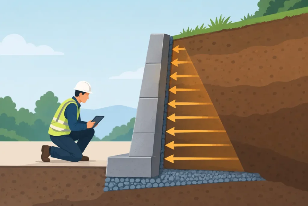
A guide to soil pressure checks starts with a distinction that is often lost in a rushed calculation: soil pressure is not a single material property to insert into a formula. It is the response of a ground model to stress changes, water conditions, wall movement and construction sequence. For retaining structures, getting that model right usually matters more than choosing a more elaborate earth-pressure equation.
A credible check should show how the assumed ground conditions lead to lateral pressure, base contact pressure and resistance. It should also make clear what is uncertain, what movement the structure can develop, and whether drainage will remain effective for its design life.
Start with the engineering question
The phrase soil pressure checks can describe two related tasks. The first is assessing lateral earth pressures on retaining walls, sheet piles, shafts and basement walls. The second is checking the pressure distribution beneath a foundation or wall base against bearing resistance, settlement and stability requirements. They must be considered together where the retained soil, wall and founding ground interact.
Before calculation, define the structural system. A gravity wall, embedded cantilever wall, propped excavation and stiff basement wall do not mobilise the same earth-pressure state. Nor should a temporary excavation be assessed in the same way as a permanent retaining wall simply because the geometry is similar.
The design situation also changes the answer. A wall that is backfilled after construction may experience compaction-induced loading. An excavation beside an existing building may need a serviceability-led assessment, because small movements rather than ultimate collapse govern the work. A waterfront structure can be controlled by changing water levels, uplift or loss of passive resistance during scour.
Build the ground model before choosing coefficients
The calculation begins with interpreted parameters, not a table of values. Establish the stratigraphy, unit weights, groundwater regime, strength parameters, stiffness where deformation matters, and the likely variability across the structure length. Boreholes, trial pits, laboratory testing, in-situ testing and previous site experience each contribute, but none should be copied into the model without interpretation.
For drained granular soils, effective friction angle and effective unit weight commonly form the basis of lateral pressure calculations. For cohesive soils, the key question is often whether loading is drained or undrained. Short-term excavation in saturated clay may require total-stress parameters, whereas the long-term condition requires effective-stress analysis. Using a single parameter set for both conditions can be unconservative or unnecessarily costly.
Groundwater deserves its own line in the calculation model. Water pressure acts independently of effective soil pressure. A drained backfill may produce lower lateral loading, but only while drainage paths remain open and discharge is possible. If filters clog, outlets are not maintained, or a perched water table develops, the wall may see hydrostatic pressure that was never included in the structural design.
Select the pressure state that the wall can mobilise
At-rest, active and passive pressures represent different movement conditions. They are not interchangeable design options.
At-rest pressure applies where the wall is sufficiently restrained that the soil cannot expand laterally to mobilise active conditions. Stiff basement walls tied to floor slabs are common examples. The coefficient at rest, often represented as K0, is influenced by stress history and overconsolidation as well as effective friction angle. A normally consolidated approximation may be inappropriate in heavily overconsolidated clay or fill with an uncertain placement history.
Active pressure is mobilised when the wall moves away from the retained ground by enough to reduce lateral stress. The required movement depends on soil type, wall roughness, density and geometry. A flexible cantilever wall may approach active conditions, but a wall with limited movement due to a prop, slab or adjacent structure may not. Applying active pressure to a fully restrained wall is a familiar source of underestimation.
Passive pressure develops when the wall pushes into the ground. It is a useful component of toe resistance and embedded-wall stability, but it requires larger movement than active pressure and is particularly sensitive to disturbance, excavation level changes and groundwater. In many designs, passive resistance is reduced to reflect these uncertainties. The reduction should be explicit and consistent with the design standard, investigation quality and construction method.
A practical guide to soil pressure checks
For a simple retained height, the effective vertical stress at depth can be established from the soil layers above it. Apply the appropriate lateral pressure coefficient to obtain effective horizontal stress, then add pore-water pressure separately. Uniform surcharge produces an additional lateral component, while line loads, strip loads, traffic and crane loads may need more specific treatment depending on their position and extent.
This process is straightforward in principle, but the pressure diagram should be checked visually. A layered profile, varying water level or surcharge near the crest will rarely produce the neat triangle assumed in preliminary sketches. Plotting the components separately – soil effective stress, surcharge and water – makes errors easier to identify and provides a clear record for review.
For a retaining wall with a base, calculate the resultant vertical load and overturning moment at the foundation level. These determine the base contact pressure distribution. The resulting pressures must remain compatible with the foundation model: a full-contact linear distribution is not valid if it implies tension beneath an unanchored base. Where partial contact is expected, assess the reduced contact area and resulting peak pressure carefully.
The base check is not only a bearing-capacity exercise. High eccentricity can increase settlement and rotation even when an ultimate resistance calculation passes. Sliding resistance should be derived from realistic interface conditions and any reliable passive contribution in front of the toe. Do not count soil that may later be excavated, softened, scoured or disturbed by services installation.
Treat surcharges and construction sequence as design inputs
A retaining wall is frequently loaded by more than retained soil. Road traffic, stored materials, foundations, rail loading and construction plant can govern the result. The relevant question is not merely whether a surcharge exists, but where it acts, how long it remains and whether it can move closer to the wall during construction.
Compaction is another practical issue. Heavy compaction plant close to a wall can impose lateral stresses greater than those represented by a conventional uniform surcharge. This may govern short, lightly loaded walls and precast units during backfilling. The specification should therefore align with the assumed design loading, including plant restrictions and lift thickness where appropriate.
Construction sequence can change both resistance and load. Excavating in front of a wall removes passive support. Raising groundwater behind it adds pressure before the permanent drainage arrangement is working. Installing props or slabs changes deformation compatibility. For excavations, a staged calculation is often more representative than a single final-state force balance.
Verify ultimate and serviceability behaviour
Ultimate limit state checks address failure mechanisms such as sliding, overturning, bearing failure, global instability and structural resistance. The applicable Eurocode basis and National Annex should govern partial factors, combinations and the treatment of actions and soil parameters. The selected design approach must be applied consistently rather than assembled from familiar factors taken from different methods.
Serviceability checks ask a different question: will movement, settlement, rotation or cracking be acceptable? This can control designs close to buildings, utilities, rail infrastructure or tunnel works. Earth-pressure coefficients alone cannot predict performance where deformation is critical. Stiffness, wall installation method, support sequence and the condition of neighbouring ground need consideration.
For deep excavations and flexible retaining systems, numerical analysis may be justified. It should not replace engineering judgement. A sophisticated model with uncertain stratigraphy, unrealistic stiffness or poorly defined drainage can produce a precise-looking but unreliable result. Simple hand checks remain valuable for testing load paths, limiting cases and whether the model response is physically plausible.
Make the calculation easy to review
A technically sound soil pressure check should be easy to follow in detail. State the geometry, design levels, soil profile, water levels, material parameters, surcharge assumptions and pressure state at the start. Then present pressure diagrams, resultant forces, lever arms and stability checks in a sequence that another engineer can reproduce.
Software is most useful when it supports this chain of reasoning rather than hiding it. For engineers moving between site, office and review meetings, calculation tools on macOS and iOS can help maintain a consistent set of inputs and outputs across devices. Psicons AB develops specialised geotechnical tools around that practical need: direct input handling, transparent calculation setup and results that can be checked graphically as well as numerically.
Where ground conditions are uncertain, identify the sensitivity rather than burying it in a single conservative value. Compare credible water levels, lower-bound strength parameters, surcharge positions and loss of passive support. That work often reveals which investigation, drainage detail or construction control will reduce risk most effectively.
A soil pressure calculation earns confidence when it reflects the structure that will actually be built, the ground that is actually present and the water that may actually reach it. Keep those three realities visible throughout the check, and the numerical result becomes a defensible engineering decision rather than just a passing output.
