
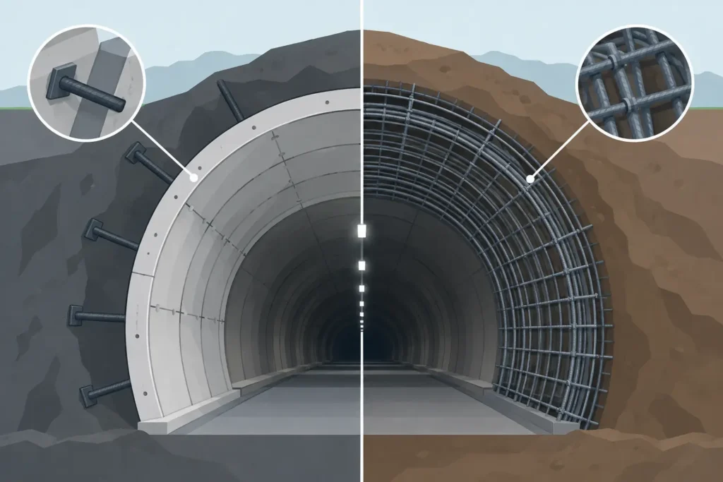
A sprayed concrete lining may be installed within minutes of blasting, while systematic rock bolts are drilled over the following round. Both are often described as tunnel stabilisation, yet they do different mechanical jobs. Understanding tunnel support versus reinforcement is therefore more than a terminology exercise: it affects the assumed failure mechanism, installation sequence, monitoring plan and the margin available when ground behaviour differs from prediction.
For a tunnelling engineer, the useful distinction is simple. Support acts at or close to the excavation boundary to retain deformation and contain loosening ground. Reinforcement improves the strength and integrity of the ground or rock mass itself. The two systems commonly work together, but they should not be treated as interchangeable in design calculations or in site decisions.
What tunnel support is intended to do
Tunnel support provides resistance at the excavation perimeter after material has been removed. Its principal role is to control convergence, prevent ravelling or block release, and maintain a stable profile until the permanent works can carry their intended load. In conventional tunnelling, support normally responds to deformation. Some movement is necessary before a lining or support ring mobilises appreciable load.
Sprayed concrete is the familiar example. Applied promptly and with adequate early-age strength, it bridges local irregularities, confines fractured rock and creates a continuous shell around the opening. Steel sets, lattice girders, mesh, straps and segmental linings also belong principally to this category. Their effectiveness depends on geometry, stiffness, continuity, connection details and the timing of installation.
Support demand is closely related to the excavation sequence. A larger unsupported span, delayed face closure or excessive round length can increase deformation before the lining becomes effective. In squeezing ground, support may need controlled yield capacity rather than simply greater stiffness. In hard but blocky rock, the critical problem may be local wedge release rather than overall convergence. The support system must suit the mechanism, not merely the tunnel class stated in a specification.
What reinforcement changes in the ground
Reinforcement introduces tensile or confinement capacity into the rock mass or soil around the opening. Fully grouted rock bolts, dowels, cable bolts, forepoling and certain umbrella systems can all reinforce ground, although their behaviour differs substantially. Their purpose may be to stitch joints together, suspend potentially unstable blocks, increase confinement, improve arching action or create a reinforced zone ahead of the face.
A reinforcement element becomes useful only when its load transfer and anchorage are credible. For a grouted rock bolt, that means considering bond along the bolt, the capacity of the steel, plate bearing where relevant, and the possibility of failure through the surrounding discontinuities. A long bolt installed across a persistent joint can be highly effective, but only if it crosses the controlling surfaces and develops load beyond the potential failure zone.
In weak ground, the term reinforcement needs particular care. Fibres in sprayed concrete reinforce the lining rather than the ground mass. Soil nails reinforce soil, but their contribution depends on pull-out resistance, facing interaction and staged excavation. Spiles may provide pre-support or reinforcement ahead of the face, depending on their layout and the ground response. Naming the product is less useful than defining the structural role it is expected to fulfil.
Tunnel support versus reinforcement in design
The distinction becomes most valuable when setting up the engineering model. A support model asks how the excavation boundary deforms and how the installed system develops reaction. A reinforcement model asks how the ground mass, discontinuities or potential failure blocks change when tensile elements are introduced.
For a circular tunnel in relatively uniform ground, a convergence-confinement approach may provide a practical first assessment of support demand. The ground reaction curve represents stress relief and deformation around the excavation, while the support characteristic represents the lining response after installation. Installation distance from the face, early stiffness and yield behaviour are central inputs.
That approach alone does not demonstrate that individual rock blocks are stable. Where jointing controls behaviour, kinematic assessment and block analysis are required. Bolts may stabilise wedges that a continuous lining cannot reliably retain without unacceptable local loading. Conversely, a bolt pattern does not necessarily replace the shell action needed to contain widespread loosening or weak, heavily fractured material.
The same principle applies to numerical analysis. Adding structural elements to a model is not enough. Their installation stage, bond model, orientation, spacing and interface assumptions need to represent the construction process. If reinforcement is activated before the excavation step that creates its demand, or sprayed concrete is assigned mature stiffness at installation, calculated displacements can be misleadingly small.
Interaction is usually the real design case
Most practical schemes combine systems. Rock bolts restrain and bind the near-field rock mass; fibre-reinforced sprayed concrete provides surface confinement and prevents small-scale ravelling; mesh or straps provide local retention where block geometry demands it. Grouting may reduce water inflow, fill open fractures and improve conditions for subsequent support, but its contribution to strength should not be assumed without evidence from the ground and the grout treatment results.
This interaction is beneficial, but it also complicates capacity allocation. It is unsafe to add nominal capacities from bolts and sprayed concrete as though both reach their design resistance simultaneously. Ground movement, installation quality, stiffness and load redistribution determine how load is shared. A sensible design identifies the governing failure modes and checks that each component has a defined role within them.
Selecting the system from ground behaviour
Ground description is the starting point, but behaviour is the decision basis. Rock mass classification can assist with initial support selection, especially during tender and early works, but it cannot replace face mapping, probing, water observations and convergence measurements. The same mapped rock quality can produce different support needs where stress, discontinuity orientation, groundwater or excavation geometry changes.
In competent massive rock, local support may be limited to scaling and selected bolts or spot sprayed concrete. The main risk is often isolated block release around intersections, crown irregularities or unfavourably oriented joints. In blocky rock, systematic reinforcement can form a stabilised shell, with sprayed concrete supplying confinement and surface retention. In very poor rock, a rapid closed support ring and short excavation advances may govern performance more than increasing bolt length.
For soft ground or mixed-face conditions, face stability and water control can become as significant as radial support. Pre-grouting, dewatering, pipe umbrellas, forepoling and staged excavation may be needed to limit loss of ground before conventional support can be installed. Here, calling every measure ‘support’ can hide a critical issue: some measures control groundwater, some reinforce the ground ahead, and some retain the excavated perimeter.
Design also has to account for durability and the permanent state. Temporary rock bolts may have a different corrosion protection requirement from permanent anchors. A sprayed concrete layer that serves as initial support may later contribute to the composite permanent lining, or it may be separated from it by a membrane. These assumptions influence thickness, reinforcement detailing, drainage and inspection requirements.
Installation quality determines the realised capacity
A well-designed support class can perform poorly if it is installed late or inconsistently. Sprayed concrete thickness varies with profile irregularity, rebound, nozzle access and operator technique. Early strength matters when the ground is moving quickly. Bolt performance depends on hole cleaning, grout quality, resin mixing where used, plate seating, installation angle and the actual anchorage length achieved.
Verification should be proportionate to the risk. Face mapping confirms whether the predicted discontinuity sets remain relevant. Pull tests, grout records, sprayed concrete cores or thickness checks, probe drilling and convergence monitoring each answer different questions. The aim is not paperwork for its own sake; it is to determine whether the design assumptions remain defensible.
Monitoring is particularly valuable because tunnel support is installed in a changing stress field. Convergence trends, crown settlement, bolt loads and sprayed concrete cracking can show whether deformation is stabilising or accelerating. Trigger levels should be linked to actions such as reducing round length, adding local support, changing the support class or reassessing the ground model. A measurement without a predefined response has limited operational value.
A practical way to avoid category errors
When reviewing a support proposal, ask first what failure mechanism is being controlled. Is it a wedge falling from the crown, progressive ravelling, squeezing convergence, face instability, water-driven loss of fines or a combination? Then ask whether each element acts as boundary support, ground reinforcement, pre-support, water control or permanent lining.
This disciplined separation makes calculations easier to review and site instructions easier to follow. It also prevents a common error: specifying more of a familiar product when the problem is actually caused by sequence, geometry or groundwater. A thicker sprayed concrete layer cannot reliably compensate for unaddressed face instability, just as longer bolts do not automatically provide a closed support ring.
Simple, transparent calculation tools are valuable here because they keep the assumptions visible. On macOS and iOS, Psicons AB develops engineering applications intended to help practitioners set up technical problems, examine inputs and interpret results without losing sight of the ground model behind the numbers.
The most useful question at the face is rarely whether a measure is called support or reinforcement. It is whether it addresses the observed mechanism, can be installed in time, and has enough verified capacity to carry its intended share of the load.
