
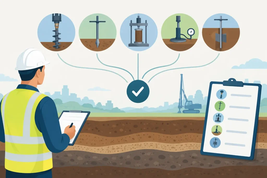
A deformation calculation can look precise while being founded on the wrong stiffness parameter. This commonly happens when soil stiffness test selection begins with the test that is available, rather than with the deformation mechanism that governs the design. A modulus measured at very small strain, for example, should not be inserted directly into a settlement analysis for a heavily loaded raft. Equally, a conventional oedometer modulus may say little about the unloading and reloading response around an excavation.
The useful question is not simply, “Which test gives a modulus?” It is: which test reproduces the stress path, strain range, drainage condition and ground variability that matter for this engineering decision?
Start with the deformation problem
Stiffness is not a single material constant. Soil stiffness changes with strain level, effective stress, stress history, structure, fabric and drainage. A test result therefore only becomes useful when its context is retained.
For a foundation settlement assessment, the relevant response may be one-dimensional compression at small to moderate strain. For a retained excavation, the important behaviour is often unloading, lateral stress relief and subsequent reloading. A tunnel may require an estimate of initial shear stiffness for ground loss assessment, followed by lower secant stiffness at the strains associated with lining installation or long-term redistribution.
Before specifying investigation work, define the expected movement and the mechanism behind it. Consider whether the design is controlled by immediate settlement, consolidation, heave, lateral wall movement, surface settlement, vibration, or cyclic loading. The anticipated strain range should be estimated, even approximately. This gives the testing programme a technical purpose and prevents a generic set of parameters being used across fundamentally different analyses.
Soil stiffness test selection by strain range
A practical way to compare methods is to consider the portion of the stiffness degradation curve they represent. The boundary between ranges is not fixed, but the distinction is essential.
Very small strain behaviour
At shear strains below roughly 0.001%, soil often exhibits its highest practical stiffness, commonly represented by the small-strain shear modulus, G0. Seismic cone penetration testing, cross-hole testing and down-hole geophysics can provide valuable information in this range. Bender elements in carefully prepared laboratory specimens may also be useful.
These methods are particularly relevant where wave propagation, vibration, dynamic response or the initial ground response around a lightly strained system is being assessed. They also provide a valuable reference point for constitutive modelling. However, G0 is not a replacement for working-strain stiffness. Using it without a defensible degradation relationship will normally underpredict deformation.
Small to intermediate strains
Pressuremeter testing, flat dilatometer testing and selected in situ loading tests can provide stiffness information closer to many serviceability problems. The strain range depends on the equipment, interpretation method and soil type, but these tests often offer a more direct representation of stress-dependent response than a single laboratory compression test.
The pressuremeter is particularly useful when lateral deformation is significant, such as in excavations, piles and tunnel-related work. Its value depends heavily on borehole quality, probe suitability and interpretation. In soft or sensitive soils, disturbance during boring can be more influential than the mathematical refinement applied afterwards.
The flat dilatometer can provide repeatable profiling and useful correlations for deformation parameters, especially where a relatively dense depth coverage is needed. It should still be calibrated against local experience and, where consequences justify it, against higher-resolution testing or monitored behaviour.
Working-strain and larger-strain behaviour
Triaxial testing and oedometer testing remain central when the loading path must be controlled and the soil’s drainage condition understood. A triaxial test can be designed to investigate stress history, anisotropy, undrained response, unloading-reloading stiffness and stress-path dependency. High-quality sampling and appropriate specimen selection are decisive.
Oedometer tests remain well suited to one-dimensional compression and consolidation questions, particularly for normally consolidated or lightly overconsolidated clays beneath broad foundations and embankments. Their limitations should be recognised where the field stress state is strongly three-dimensional, where lateral strain is important, or where sampling disturbance has altered the structure of the clay.
Plate loading tests can be highly persuasive because they measure a load-displacement response directly in the ground. Yet their zone of influence is limited by plate size and applied stress. A plate test should not automatically be extrapolated to a large foundation, deep fill platform or structure with a different stress bulb. It is a local test, not a universal answer.
Match drainage and stress path
A stiffness value has little meaning without identifying whether it is drained or undrained. In saturated clay subjected to rapid loading, an undrained shear modulus may govern short-term movements. For long-term settlement, drained stiffness and consolidation characteristics become more relevant. The same clay can therefore require different parameters for different construction stages.
Stress path matters just as much. An excavation unloads the soil before any structural reload takes place. A bored pile installation may involve stress relief, remoulding and reconsolidation near the shaft, while a driven pile can increase horizontal stresses in some soils. A tunnel face introduces three-dimensional unloading that no conventional laboratory test reproduces fully.
Where numerical analysis is used, avoid selecting a modulus merely because it corresponds to a field test with a familiar name. The model may require a tangent stiffness, secant stiffness, unloading-reloading modulus, constrained modulus or shear modulus. These are related, but they are not interchangeable. The parameter should match both the constitutive model and the design scenario.
Build a programme around ground variability
No individual test method resolves variability across a project site. This is why a combined approach is usually more defensible than relying on a small number of expensive, isolated measurements.
Cone penetration testing can establish continuous stratigraphic and resistance profiling, identify changes in soil behaviour and guide the locations of sampling or specialist in situ tests. CPTu data are especially useful when pore pressure response helps distinguish layers and interpret drainage behaviour. They also support correlations, although correlations should be treated as estimates whose reliability depends on local geology and calibration.
High-quality samples then allow targeted laboratory testing where stress history, permeability, creep, strength and stiffness need closer examination. Pressuremeter or dilatometer testing can fill the gap between broad profiling and laboratory control. Geophysical measurements can provide a wide spatial picture of small-strain stiffness and identify zones that deserve further investigation.
The proportion of each method depends on the project. A shallow warehouse extension on relatively uniform dense sand does not justify the same programme as a deep basement in soft clay or a rail tunnel through alternating glacial deposits and fractured rock. The objective is not to collect every available parameter. It is to reduce the uncertainty that has the greatest influence on design movement and construction risk.
Treat sample quality as a design input
For cohesive soils, a sophisticated laboratory programme cannot repair poor sample quality. Stress relief, extrusion, transport, storage and trimming may reduce measured stiffness and strength, particularly in structured or sensitive clays. Signs of disturbance should be recorded and discussed, not hidden behind a single representative value.
In situ tests avoid some sampling effects but introduce other sources of uncertainty. Borehole disturbance affects pressuremeter results. Equipment calibration, rate of loading, membrane corrections, penetration effects and operator procedure all influence the outcome. Good soil stiffness test selection therefore includes a quality plan: specify test standards, acceptance criteria, calibration records, logging requirements and the level of interpretation expected from the ground investigation team.
Use correlations carefully, then verify them
Correlations from CPT, SPT, shear-wave velocity or index properties are often necessary at early design stages. They can provide reasonable first estimates when paired with geological understanding and an appropriate range of values. Their weakness is false precision. A published equation cannot know whether the material is cemented, aged, fissured, organic, partially saturated or affected by a local depositional history.
For consequential serviceability decisions, use correlations to establish an initial model and then verify the governing layers with direct testing, observational data or both. During construction, settlement markers, inclinometers, extensometers and pore pressure instruments can be used to compare predicted and measured behaviour. This is particularly valuable where staged construction, dewatering or excavation support creates stress paths that are difficult to replicate in a test programme.
Make parameters traceable in the calculation
A design report should show more than a table of moduli. For every adopted stiffness parameter, state the soil unit, depth interval, test source, drainage condition, stress range, strain range and intended use in the analysis. If a value has been derived from a correlation or adjusted for model input, record the basis.
This traceability makes review easier and reveals where assumptions dominate. It also makes later updating straightforward when additional investigation or monitoring becomes available. Simple, transparent parameter management is often more valuable than an elaborate calculation built around poorly documented inputs.
For engineers working between site, office and review meetings, a calculation workflow that keeps test data, assumptions and graphical outputs together reduces the risk of losing this context. Psicons AB develops straightforward geotechnical tools for that type of technical work across macOS and iOS.
The best testing programme is rarely the one with the most data. It is the one that gives the design team confidence that the selected stiffness represents the ground response at the strain level and construction stage where movement actually matters.
