
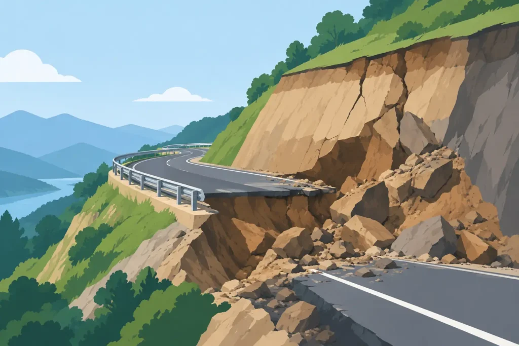
A road cutting can appear stable at handover and still fail after the first sustained period of rainfall. This road cutting failure case study examines that familiar sequence: a localised slope collapse in a newly widened road corridor, where the immediate trigger was water but the underlying causes were geological interpretation, excavation sequence and incomplete support.
The case is representative rather than tied to a named project. Its value lies in the engineering decisions that can be examined after the event. Road cuttings rarely fail for one reason alone. Failure normally develops where ground conditions, groundwater and construction activity interact in a way that was not fully captured in the original model.
The road cutting failure case study
The cutting was formed to widen a two-lane rural road through a hillside of residual soil over weathered rock. The final cut was approximately 11 m high, with a nominal overall slope of 1V:1.5H. Initial ground investigation described stiff sandy clay with cobbles over fractured bedrock. The design assumed that the residual soil would stand temporarily at the proposed inclination and that permanent drainage measures could be installed after bulk excavation.
During excavation, the contractor encountered a 1 to 2 m thick horizon of highly weathered, clay-rich material between the apparent soil and the more competent rock. In places, this horizon contained relict joints and sheared seams dipping out towards the road. The material was logged as weathered rock in some excavation records and as clayey soil in others. That distinction mattered. Its shear strength under drained conditions was lower than the parameters adopted for the nominal rock mass, and its permeability contrast with the underlying rock created a natural route for perched water.
The cutting stood through a relatively dry construction period. Surface channels were incomplete, and several temporary drainage measures discharged close to the crest rather than beyond it. Following prolonged rainfall, small tension cracks appeared behind the crest. Two days later, a section roughly 25 m long displaced along the weak horizon, depositing soil, weathered rock and vegetation across one lane.
No injury occurred, but the road closed and emergency stabilisation was required. The direct cost was significant. More consequentially, the programme was delayed while the failed mass was removed, the slope re-investigated and the support concept revised.
Failure was progressive, not sudden
The visible collapse was the final stage of a progressive process. Excavation had removed toe restraint and exposed a variable geological profile. The weak horizon was not continuous everywhere, but where it daylighted in the affected section it formed a plausible sliding surface. Rainfall then increased pore water pressures above the less permeable underlying material, reducing effective stress and available shear resistance.
A simple effective-stress expression remains useful when reviewing such events: shear strength depends on effective normal stress, not total normal stress alone. As pore pressure rises, effective normal stress falls. In a clay-rich shear zone, even a modest pressure increase can move a marginal slope towards failure.
The original stability check used representative material zones and a groundwater level below the proposed slip surface. That was reasonable only if the ground model was correct and drainage controlled the water regime as assumed. Neither condition held consistently across the cutting. The analysis also treated the excavation as a final geometry problem. It did not adequately test the temporary stage in which the slope was open, drainage unfinished and rainfall exposure unavoidable.
This is a recurring weakness in road projects. Permanent works may satisfy a calculated factor of safety while the construction sequence creates a lower, unexamined temporary factor of safety. The distinction is especially relevant in heterogeneous residual soils, weathered rock and old landslide terrain.
Where the investigation and design fell short
The investigation spacing was adequate for broad route selection but too coarse for defining variability along the specific cutting. Boreholes had identified weathered material, yet they did not resolve its continuity, thickness or structural orientation. Exposure mapping during excavation could have improved the ground model, but the observations were not systematically translated into a revised stability assessment.
There was also an issue of classification. Calling a material “weathered rock” does not assign it rock-like behaviour. Where a weathered zone is decomposed, clay-filled or traversed by persistent discontinuities, its behaviour may be better represented by soil strength parameters, discontinuity shear strength, or both. Selection depends on the expected failure mechanism. A circular or composite soil failure and a translational failure along a weak seam require different models and different evidence.
Drainage design was treated as an accessory item rather than part of the stability system. Crest drainage was not completed before the final cut was exposed. Temporary diversion was vulnerable to blockage, and there was no verified route for water emerging from the weathered contact. Surface water management cannot remove all subsurface risk, but it can prevent infiltration from adding to it.
Finally, there was no defined trigger-action response plan. The tension cracks were recognised, but the site team did not have agreed thresholds for stopping work, restricting traffic, surveying movement or calling for a geotechnical review. Cracks near a cut crest do not always lead to collapse. They do, however, require prompt assessment when they coincide with rainfall, seepage or fresh material exposure.
Back-analysis changed the support concept
The post-failure investigation combined face mapping, trial pits above the crest, targeted boreholes, installation of standpipes and review of rainfall records. The purpose was not merely to explain the collapse. It was to identify a defensible remedial design and establish whether adjacent sections shared the same risk.
Back-analysis considered a composite sliding mechanism following the weathered horizon and daylighting at the lower slope. Parameters were calibrated within the range supported by laboratory testing, field observations and published experience of comparable materials. The exercise indicated that the slope was close to limiting equilibrium before the rainfall period. Raised pore pressures then reduced stability below an acceptable level.
A deterministic limit-equilibrium analysis was appropriate for rapid comparison of geometry, drainage and reinforcement options. It did not remove uncertainty. For the most variable sections, sensitivity analyses were more informative than a single reported factor of safety. Varying the weak-layer friction angle, cohesion, groundwater level and depth of tension cracking showed which assumptions controlled the outcome.
The remedial solution combined flattening where land take permitted, removal of the weakest near-surface material, crest interception drains, horizontal drains targeted at the perched water zone, and soil nails with facing in the constrained central section. In the lower part of the cutting, a buttress was used to restore toe support. This was not the cheapest arrangement in isolation, but it reduced reliance on a single intervention and accommodated the remaining geological uncertainty.
Instrumentation was retained through the wet season. Piezometers confirmed whether the drains were reducing pore pressures, while survey points provided a straightforward check on deformation. Monitoring is most useful when it answers a defined question. In this case, the questions were whether water levels responded to rainfall as expected and whether movement had stabilised after the remedial works.
Practical lessons for future road cuttings
The main lesson is not that every road cutting requires extensive reinforcement. Many can be safely formed with sensible geometry and drainage. The lesson is that the design must reflect the failure mechanism that the ground can plausibly support, including the temporary condition.
For a proposed cutting in variable ground, engineers should treat the exposed face as new information rather than merely a construction record. Geological mapping, photographs, discontinuity measurements, seepage observations and records of changing materials should feed back into the geotechnical model. A change in material classification, weak-layer orientation or groundwater behaviour can justify a revised analysis before excavation proceeds further.
Drainage should be designed and sequenced as a stability measure. Crest channels need positive falls and maintainable outlets. Temporary water control must remain effective during construction, not only after landscaping is complete. Where perched water is possible, the investigation and design should consider how water reaches the weak horizon and where it can safely be relieved.
Analysis tools should support transparent checking, not conceal uncertainty behind a single output. A clear calculation record should show geometry, load cases, water assumptions, strength parameters, search method and sensitivity cases. Straightforward graphical outputs can make it easier for the designer, reviewer and site team to see whether the proposed slip surface follows a credible geological feature. This is one reason specialised geotechnical software, including tools developed by Psicons AB for macOS and iOS workflows, should favour clear input handling and results that are easy to follow in detail.
The most useful closing thought is practical: when a cutting begins to show cracks, seepage or unexpected weak material, treat it as evidence that the ground model is being tested. Pause long enough to understand that evidence. A timely revision to drainage, geometry or support is usually far less disruptive than recovering a failed slope.
