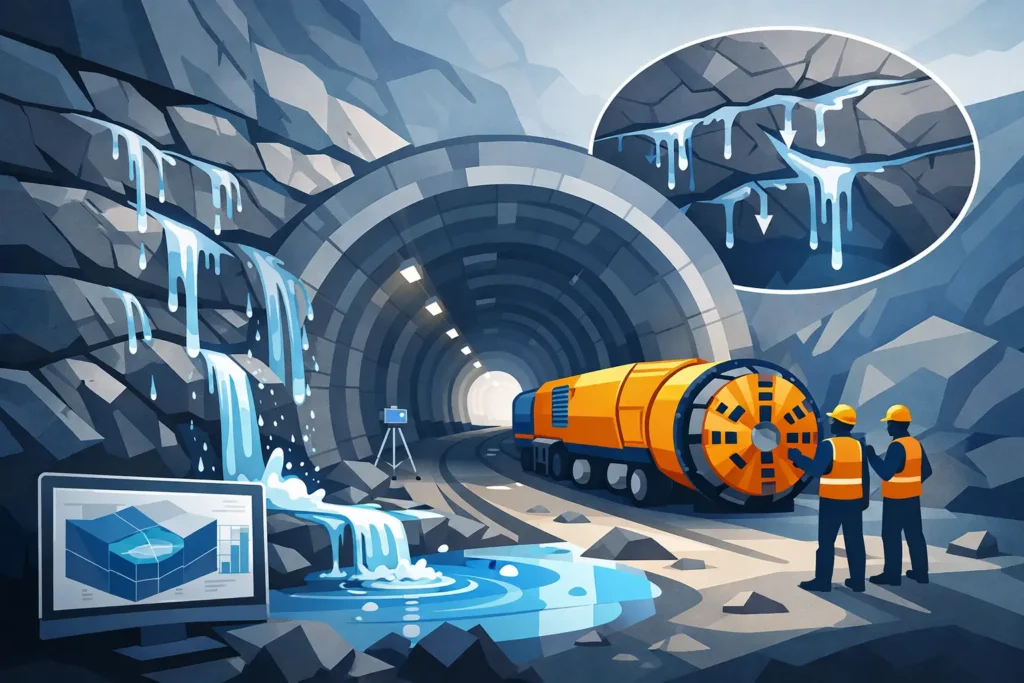
A predicted inflow of 5 L/min may be insignificant for one tunnel heading and a critical problem for another. The difference is not only the total water volume. It is the location of the inflow, the pressure response, the sensitivity of the ground, the construction method and the consequences for adjacent groundwater systems. Knowing how to model tunnel inflow therefore means building a defensible representation of the ground and testing the decisions that matter, rather than producing a single reassuring number.
For rock tunnels, inflow modelling is commonly used to support route selection, pre-grouting design, drainage strategy, environmental assessment and contractual risk allocation. The calculation should be simple enough to inspect, but detailed enough to reflect the controlling hydrogeological features. That balance depends on the project stage and the available evidence.
Start with the decision, not the equation
Before selecting an analytical solution or numerical model, define what the model must answer. A feasibility-stage model may need an order-of-magnitude estimate of inflow per kilometre and likely drawdown. A detailed design model may instead need to compare grouting classes, estimate residual inflow to a specific tunnel reach, or assess effects at a spring, well or sensitive structure.
This distinction governs the appropriate model complexity. A three-dimensional groundwater model with poorly constrained fracture properties can give a visually impressive result without reducing uncertainty. Conversely, a well-documented analytical model can be entirely appropriate where the tunnel geometry is regular, the rock mass is reasonably homogeneous at the scale of interest, and the aim is to compare alternatives.
State the prediction targets explicitly. They may include steady-state inflow, transient inflow during excavation, drawdown at observation points, inflow to shafts and cross-passages, or the effectiveness required from pre-excavation grouting. Also define whether the result is expected as an average value, a credible upper design case, or a range for risk management.
Build the conceptual ground model first
The conceptual model is the foundation of tunnel inflow analysis. It describes how water enters, moves through and leaves the system. It should be drawn and discussed before it is coded or calculated.
For a hard-rock tunnel, the relevant features commonly include topography, overburden, soil deposits, rock domains, major fracture zones, fracture sets, faults, water-bearing contacts, surface water and groundwater recharge areas. Hydraulic boundaries require particular care. A lake may behave as a constant-head boundary, a low-permeability valley fill may limit recharge, and a major fracture zone may either transmit water efficiently or be sealed by mineralisation and clay gouge.
The tunnel itself is not always a simple drain. Its hydraulic behaviour changes with excavation sequence, probe drilling, grouting, lining, drainage details and the degree of connection between the excavation damage zone and the surrounding fracture network. A model that treats every tunnel section as equally permeable and equally drained may be useful for screening, but it should not be mistaken for a detailed representation of construction conditions.
Characterise hydraulic conductivity at the right scale
Hydraulic conductivity is often the parameter that dominates predicted inflow, yet it is also one of the most variable. Packer tests, water pressure tests, borehole flow logs, pumping tests and inflow observations provide valuable data, but each samples a different volume of rock and may be influenced by drilling disturbance, test pressure and fracture connectivity.
Do not simply average test values. Consider their spatial distribution, the geological domain, test length, depth and relationship to mapped structures. A median value may describe background rock, while the upper part of the distribution may be more relevant for a conservative design case. Inflow is frequently controlled by connected conductive features rather than by the average condition of the entire rock mass.
An equivalent porous medium approach can be appropriate for regional drawdown or early-stage estimates. Discrete fracture or hybrid models may be justified where individual zones, fracture sets or tunnel intersections control the outcome. The choice should follow the conceptual model, not software preference.
Select a calculation method that matches the problem
Analytical methods remain valuable for tunnel inflow because they are transparent and quick to test. For a circular tunnel in a homogeneous, isotropic aquifer, radial-flow solutions can provide a useful first estimate. Input assumptions are visible, sensitivity is easy to assess and results can be checked by hand.
However, these solutions become less reliable where the tunnel is shallow beneath an irregular water table, close to a recharge boundary, intersects major zones, or is constructed in strongly anisotropic fractured rock. They may also overstate long-term inflow if grouting and lining are effective, or understate local peak inflows where a conductive feature is intersected.
Numerical groundwater models are useful when geometry, boundaries and heterogeneity materially affect the result. They can represent staged excavation, spatially variable permeability, drainage tunnels, shafts, surface-water interaction and transient recharge. Their value lies in testing physically plausible scenarios, not in creating false precision. Mesh refinement around the tunnel, boundary placement and the representation of tunnel drainage should all be checked through sensitivity testing.
For many projects, the most useful approach is staged. Begin with analytical estimates to establish scale and identify sensitive assumptions. Use a numerical model only where its additional resolution will change a design, environmental or contractual decision.
Represent grouting as a hydraulic intervention
Pre-excavation grouting is often central to the inflow problem. It changes the hydraulic conditions around the tunnel, but its effect is not represented credibly by assigning an arbitrary low permeability to a ring of rock.
The grouted zone should be defined by its intended thickness, overlap, borehole geometry, target residual transmissivity and expected variation between rock classes. The model should distinguish between background rock, conductive structures and the treated zone. A grout curtain can be highly effective in fractured rock while offering limited improvement where a dominant water pathway lies outside the treated envelope or bypasses it along a fault.
Where test sections or previous headings are available, use observed pre- and post-grouting water losses and tunnel inflows to constrain the assumed treatment effect. The relevant question is usually not whether grouting reduces permeability in principle, but whether it reduces inflow sufficiently at the tunnel scale under realistic construction control.
Use scenarios rather than one “best estimate”
A single calibrated parameter set can conceal the uncertainty that project teams need to manage. Present a small number of named cases based on the conceptual model: a lower inflow case, a central case, an upper inflow case and, where relevant, a focused fracture-zone intersection case.
Each case should vary parameters together in ways that remain geologically credible. For example, a high-conductivity rock mass may also imply stronger hydraulic connection to a lake or fracture zone. Varying only one parameter at a time is useful for diagnosis, but it can create combinations that do not represent a plausible ground condition.
Results should include more than tunnel inflow. Plot or tabulate drawdown, hydraulic gradients near sensitive receptors, flow entering different tunnel sections and the contribution from identified zones. These outputs make it easier for geologists, designers and construction teams to identify where mitigation is actually needed.
Calibrate against observations, then retain uncertainty
Calibration should use all relevant observations: groundwater levels, flow logs, packer-test trends, spring discharges, pumping-test responses, probe-hole water losses and measured tunnel inflow. Match the spatial pattern as well as the total flow. A model that reproduces total inflow by compensating for errors in separate tunnel sections is not necessarily reliable for local design.
Calibration does not remove uncertainty. It narrows the range of models consistent with the available evidence. Document parameters that were adjusted, observations that could not be matched, and explanations for discrepancies. This record is essential when conditions change during excavation or when results are reviewed in a contractual setting.
Make the model useful during construction
Tunnel inflow modelling is most valuable when treated as a living engineering tool. Update the conceptual model as probe drilling, mapping and water observations reveal actual conditions. Compare predicted and measured inflow by chainage and geological domain, not only as a project total. A local mismatch may indicate an unmapped structure, ineffective grouting or an incorrect boundary assumption.
Practical calculation software should support this workflow with straightforward input handling, traceable assumptions and graphical and text-based output that can be reviewed on site or in the design office. Psicons AB develops specialist tools for engineers who need this type of focused technical work across macOS and iOS devices.
The most reliable tunnel inflow model is not the largest one. It is the model whose assumptions can be explained, whose uncertainty is visible and whose predictions are tested against the ground as excavation proceeds.