
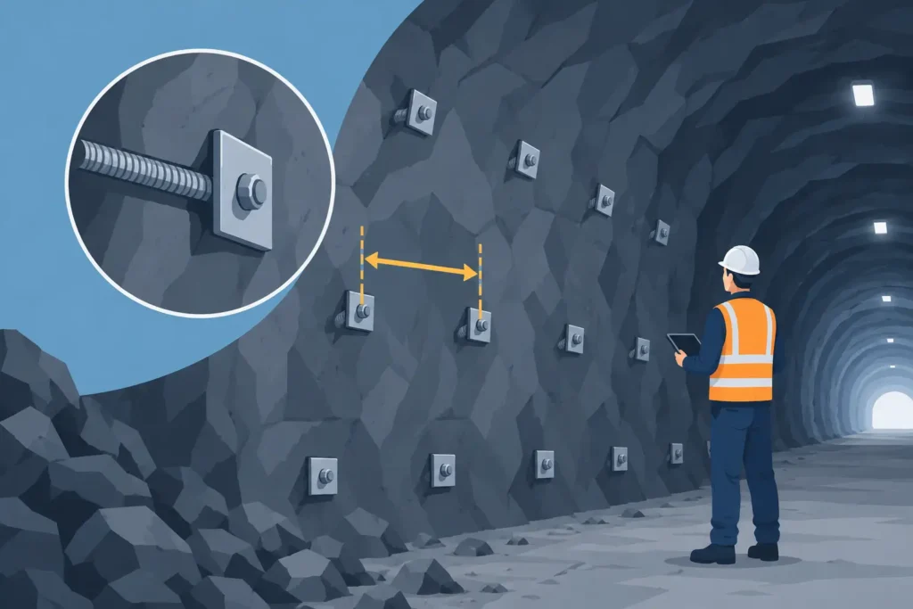
A rock support pattern can look regular on a drawing yet behave very differently underground. Rock bolt spacing is not simply a geometric choice between rows and columns: it determines how the rock mass arches, how wedges are restrained, how surface displacement develops and how much tolerance exists when geology changes between rounds.
For tunnel, cavern and mine excavation, the appropriate spacing is therefore a design outcome. It must follow the anticipated failure mechanisms, rock mass condition, excavation sequence and support system, then be checked against what is actually exposed at the face. A nominal pattern is useful for installation. Treating it as fixed regardless of conditions is not.
What rock bolt spacing is intended to achieve
Rock bolts work by creating confinement and reinforcement within a fractured rock mass, or by tying potentially unstable blocks and wedges to more competent ground. Spacing controls whether individual bolts act as isolated point restraints or as a connected support system with sufficient coverage across the excavation perimeter.
When bolts are too widely spaced, loosened rock can deform or detach between them. The support system may still have substantial capacity on paper, but it does not intercept the relevant joints, discontinuities or rock blocks. When bolts are very closely spaced, the support may improve confinement and reduce deformation, but at a cost in drilling time, consumables, congestion and possible damage to the rock from excessive drilling.
The target is not the smallest possible spacing. It is a pattern that provides reliable load transfer and coverage for the expected ground response, while remaining installable within the time available after each blast or excavation pass.
Spacing must also be considered with bolt length and capacity. Short, closely spaced bolts may provide effective near-surface retention but cannot anchor beyond a deep-seated loosened zone. Long bolts at wide spacing may cross the potential failure surface but leave local blocks insufficiently restrained. The support design needs both appropriate penetration and adequate areal density.
Rock bolt spacing starts with the failure mechanism
A useful first question is: what is expected to fail if no support is installed? The answer should guide the bolt layout more directly than a generic spacing table.
In blocky rock, structurally controlled wedges are often the governing concern. Joint orientation, persistence, roughness, infill and water conditions determine whether a wedge can daylight into the roof or wall. Bolts should intersect and restrain the relevant discontinuities. A square pattern may be practical, but a locally adjusted pattern can be necessary where the wedge geometry is unfavourable.
In heavily fractured or weathered rock, the issue may be progressive loosening rather than one distinct block. Here, tighter and more uniform coverage is usually needed to develop confinement and maintain a reinforced shell around the excavation. Mesh, fibre-reinforced sprayed concrete or both may be required between bolts, because bolt spacing alone cannot retain small fragments at the surface.
For stress-driven conditions, the design question changes again. Slabbing, spalling and stress-induced fracturing can extend behind the excavation boundary, particularly in the crown and shoulders. Bolt length, stiffness, installation timing and the interaction with sprayed concrete become central. Reducing spacing can help, but it is not a substitute for reaching beyond the damaged zone or managing the excavation sequence.
Parameters that influence the layout
Rock mass classification systems can provide a disciplined starting point for support selection. Q-system, RMR and GSI-based approaches are widely used to relate observed ground quality to support categories. They should be treated as aids to engineering judgement, not as automatic design engines. The same classification value can conceal very different joint geometries, stress conditions and water behaviour.
The excavation span matters because increasing span generally increases the volume of potentially loosened rock and the demand on the support system. The crown, shoulders and walls should not automatically receive identical treatment. The shoulders are frequently sensitive zones, combining high curvature, changing stress conditions and unfavourable discontinuity daylighting.
Bolt type also affects practical spacing. Fully grouted rebar bolts, friction bolts, expandable bolts and cable bolts develop load differently and have different installation tolerances, corrosion provisions and suitability for specific ground conditions. Their stated capacity is only one part of the decision. Bond length, grout quality, hole condition and the competence of the anchorage zone all influence the load that can be mobilised.
Installation quality cannot be separated from design. Hole deviation can leave bolts poorly oriented relative to the intended joint set. Variable hole depth, inadequate cleaning, incomplete grouting and poor face access may reduce performance. A layout with slightly more conservative spacing may offer useful resilience where these practical limitations are expected, but it should never be used to excuse uncontrolled workmanship.
From nominal pattern to a workable support design
A nominal spacing is commonly established for each ground support class, then adjusted through observational control. This makes construction instructions clear without ignoring the fact that ground conditions are variable.
Begin by defining the excavation geometry and the expected ground domains. Review core logging, mapping, probe drilling, geophysics where relevant, nearby exposures and the anticipated in-situ stress regime. Identify whether the key risk is wedge release, ravelling, stress damage, squeezing behaviour or a combination of mechanisms.
The next step is to select bolt length, type, inclination and spacing as a complete system. For a structurally controlled wedge, bolt orientation may be more valuable than simply reducing the grid dimension. For a fractured crown, a regular pattern with adequate overlap and surface support may be the better solution. At interfaces between rock classes, transitional patterns are often preferable to abrupt changes that leave a locally unsupported strip.
The pattern should then be checked by more than one method. Kinematic analysis is valuable where joint-controlled instability is likely. Wedge analysis can estimate block geometry and bolt demand. Empirical methods provide benchmarking against relevant excavation experience. Numerical analysis may be justified for complex geometry, high stress, large caverns or where support interaction and deformation are significant. Each method has limitations, so agreement between methods is more informative than apparent precision from one model.
At Psicons AB, the practical value of calculation software lies in making such checks straightforward to set up, review and communicate across macOS and iOS devices. The engineering decision still depends on the assumed geology, the chosen failure mechanism and critical interpretation of the result.
Field observations should change the pattern when needed
The face mapping and support record are part of the design process, not merely construction documentation. Conditions that justify a review include increased joint frequency, persistent clay-filled seams, wet zones, overbreak, audible cracking, unexpected convergence, poor grout returns or damage around installed support.
Observational design requires agreed trigger levels and a clear route for action. If mapping identifies a wedge outside the assumed structural domain, the response may be additional spot bolts, altered bolt orientation, tighter spacing, longer bolts or increased sprayed concrete thickness. The correct response depends on the observed mechanism. Adding bolts indiscriminately can consume time without resolving the actual instability.
Monitoring gives a further check on whether the installed pattern is performing as intended. Convergence measurements, extensometers, bolt load monitoring and visual inspections can indicate whether deformation is stabilising. Readings must be interpreted alongside excavation progress, blasting effects and groundwater changes. A single movement value without context rarely provides a sound basis for altering support.
Common errors in specifying bolt patterns
One recurring error is describing spacing without specifying the support zone. A statement such as “bolts at 1.5 m spacing” is incomplete unless it identifies the crown, shoulders, walls, face or local treatment area, as well as bolt length and installation orientation.
Another is relying on centre-to-centre spacing while overlooking edge distance. The support pattern needs to cover the perimeter adequately, particularly at the springline, around openings and near geometric changes. Leaving a large gap at the boundary can undermine an otherwise sensible grid.
A third error is assuming regular spacing means uniform demand. Ground is rarely uniform. Local reinforcement around intersections, niches, portals, faults and changes in span is commonly needed. Conversely, conservative support installed everywhere may be difficult to justify if mapping and monitoring show sustained competent conditions.
Finally, bolt spacing should not be designed in isolation from sprayed concrete, mesh, lattice girders or steel sets. These elements share load differently over time. A design that depends on surface support to bridge between bolts must state the required sprayed concrete thickness, reinforcement and installation sequence clearly.
Designing for control, not just compliance
Good rock bolt spacing is easy to communicate on drawings, realistic for the installation crew and traceable back to a defensible ground model. It provides enough flexibility for the engineer to respond to actual conditions without turning every round into a redesign exercise.
The most useful support specification therefore combines a clear baseline pattern with defined observational checks and pre-agreed adjustment rules. That approach respects the uncertainty inherent in underground works while keeping design, construction and interpretation focused on the behaviour of the rock mass itself.
