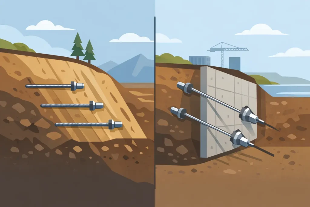
A temporary excavation beside an operating road may appear to need only a retaining wall. The design decision is more fundamental: should the ground mass be reinforced progressively as excavation proceeds, or should the wall be restrained by prestressed elements extending behind it? Soil nails versus ground anchors is therefore not simply a comparison of two reinforcement products. It is a comparison of different structural actions, construction sequences and assumptions about ground behaviour.
Both methods can support cuts, stabilise slopes and limit deformation. Both require a credible ground model, adequate facing and careful drainage. Yet applying the same design logic to each can produce misleading results, particularly where displacement limits, groundwater or property boundaries control the scheme.
Soil nails versus ground anchors: the basic distinction
Soil nailing reinforces a potentially unstable soil mass using closely spaced, usually passive inclusions installed in stages from the exposed excavation face. As the soil deforms, shear and tensile forces mobilise along the nail-soil interface. The nailed ground and facing act together as a composite retaining system.
Ground anchors, often called tieback anchors, are generally active elements. A tendon is installed through the retaining wall or facing and into a defined bond length beyond the potential failure zone. It is then prestressed and locked off at a specified load. That prestress applies a deliberate stabilising force before substantial wall movement is required.
This distinction matters. A soil nail obtains much of its resistance after movement occurs. An anchor can limit movement from an earlier stage, provided the anchor head, free length, bond zone and retaining structure are designed and constructed correctly. Neither approach is automatically safer or more economical. The appropriate choice depends on the ground, the geometry and the performance required.
How the systems carry load
Soil nails mobilise resistance through deformation
Nails are commonly installed at a slight downward inclination, in a regular grid, with a sprayed concrete facing or another suitable surface support. The potential sliding mass develops tensile loading in the nails as it moves relative to the stable ground behind it. Bond resistance along the grouted length transfers that load into the surrounding soil.
Design must consider global stability, internal stability and facing behaviour. Nail tensile capacity, pull-out resistance, corrosion allowance, connection capacity and the interaction between nail layout and possible slip surfaces all require checking. The assumed bond strength should be tied to the geological model and, where uncertainty is material, verified through testing.
The method works particularly well where staged excavation is practical and some controlled deformation can be accepted. It is often attractive for cut slopes and temporary excavations in competent granular soils, stiff clays or weathered rock. However, loose saturated soils, highly sensitive clays, soft organic deposits and ground subject to uncontrolled seepage can make both installation and performance less predictable.
Ground anchors apply an active restraint
An anchored wall may be formed from sheet piles, secant piles, contiguous bored piles, diaphragm walls or a structural sprayed concrete facing, depending on the excavation and ground conditions. The anchor load is transferred from the wall through the tendon to a grouted bond length located in competent ground.
The free length is intended to remain unbonded so that the prestressing force reaches the bond zone. The bond zone must sit beyond the relevant failure surface and must have sufficient capacity for the design load. Its performance depends on ground type, drilling method, grout placement, bond length, stress changes and the quality of installation.
Because anchors can be stressed at each excavation level, they are often selected where wall deflection must be tightly controlled. This may apply next to rail infrastructure, utilities, sensitive masonry, deep basements or tunnel structures. The greater control comes with additional design, testing and observational requirements. An anchor system is only as reliable as its load transfer, lock-off procedure and long-term protection strategy.
Construction sequence changes the answer
The construction programme is often the deciding factor. Soil nailing is normally installed top-down: excavate a shallow lift, install the nails, apply facing, then continue. This sequence suits open cuts where the face can remain stable long enough for each stage to be completed.
Anchored retaining walls are also frequently built top-down, but the wall is commonly installed before bulk excavation. At each level, the contractor excavates to the anchor horizon, drills and grouts the anchors, waits for grout strength where required, proof tests or performance tests the anchors, stresses them and then continues excavation. The procedure introduces hold points, but it can provide a better-controlled support condition for deeper excavations.
Access is a practical constraint in both cases. Soil nails require drilling from the excavation face. Ground anchors need access for drilling rigs and stressing equipment, as well as sufficient space beyond the wall for the anchor length. Near a boundary, an anchor may pass below neighbouring land or infrastructure. That creates legal, operational and technical constraints that can rule out the method even where it is structurally favourable.
Groundwater and drainage are not secondary details
Water can alter effective stress, increase driving forces, reduce bond resistance and create erosion paths behind a facing. A design that treats drainage as an afterthought is vulnerable regardless of whether it uses nails or anchors.
For soil-nailed slopes and cuts, surface water management, drainage layers, weep holes and measures against clogging may be central to the system’s performance. Local perched water can be more relevant than a regional groundwater level, particularly in layered glacial soils or weathered rock.
For anchored walls, groundwater pressures affect wall actions, anchor demand and the excavation’s basal stability. Dewatering can reduce pressures, but it may also cause settlement outside the excavation. Cut-off walls, recharge arrangements and staged pumping should therefore be assessed as parts of the overall geotechnical scheme, not as site conveniences.
Deformation criteria should be stated early
A common mistake is to choose a support system from calculated factors of safety alone. Stability is essential, but movement may be the governing criterion. A cut beside an empty plot and a cut beside a century-old building do not have the same acceptable performance, even if their geometry is similar.
Soil nailing can tolerate and requires some strain to mobilise its stabilising action. This does not mean it is unsuitable near assets, but predicted movements need realistic assessment and the consequences must be acceptable. Wall stiffness, nail length, spacing, facing details, excavation lift height and groundwater condition all influence the result.
Ground anchors can reduce early movement through prestress, but they do not eliminate deformation. Wall installation, excavation unloading, anchor stressing, ground variability and time-dependent behaviour can still cause displacement. In soft clays, for example, consolidation and creep may govern the long-term response. Anchor lock-off loads and monitoring plans should reflect that possibility.
Verification distinguishes a design from an assumption
Both systems benefit from observational design. Initial calculations define a feasible arrangement, but field measurements show whether the ground is behaving as expected. Inclinometers, survey targets, load cells, piezometers and regular face inspections can provide the evidence needed to continue safely or adjust the works.
Anchor testing has a particularly formal role. Suitability tests, proof tests and acceptance criteria help confirm that the bond zone can carry the intended load and that creep is within the project requirements. Test anchors should represent the anticipated range of ground conditions, not merely the most convenient location.
For soil nails, trial installations and pull-out tests can calibrate the design bond resistance. Installation records are equally valuable: drilling conditions, grout take, nail length, inclination and any voids or loss of return may reveal changes in the ground model. A digital calculation workflow is useful when these site observations require rapid updates to geometry, loads or assumed parameters.
Selecting the practical solution
Soil nailing is often favourable when a slope or open cut can be excavated in lifts, reinforcement can remain within the site boundary, and modest movement is acceptable. It can use relatively light equipment and can be economical where the ground provides dependable nail bond.
Ground anchors are often favourable for deep excavations, stiff retaining walls and projects with demanding movement limits. They are also useful where an active support force is required at a particular level. Their disadvantages include the need for anchor rights, specialist stressing and testing, and long-term durability provisions if anchors remain permanent.
The comparison is not always binary. A project may use nails for local slope stabilisation, anchors for a deep wall section and passive reinforcement or internal bracing where off-site anchorages are impossible. The ground model, construction sequence and monitoring strategy should be developed together rather than handed between separate design stages.
The most useful question is not which system is generally better. It is which mechanism best matches the allowable movement, available footprint, groundwater regime and construction control on the actual site. When those conditions are explicit, the choice between soil nails and ground anchors becomes easier to calculate, easier to build and easier to verify.