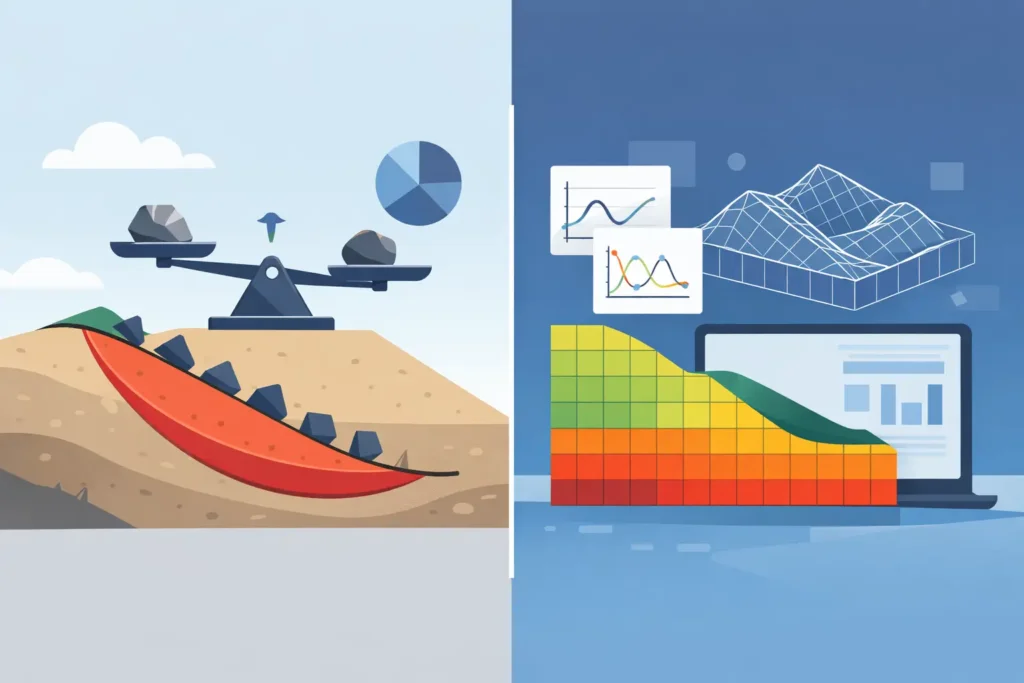
A calculated factor of safety can look reassuring on a drawing while concealing the mechanism that will control movement on site. That distinction sits at the centre of limit equilibrium vs numerical modelling. Both methods are established parts of geotechnical practice, but they answer different questions and demand different levels of data, judgement and checking.
For routine slopes, embankments and excavations, limit equilibrium analysis is often the clearest route to a transparent design decision. For staged construction, interaction with structures, highly variable ground, or deformation-sensitive works, numerical modelling may add insight that a factor of safety alone cannot provide. The appropriate choice is not a contest between old and new methods. It is a decision about the engineering question, the consequences of being wrong and the evidence available to support the model.
What limit equilibrium analysis does well
Limit equilibrium methods assess whether a potential sliding mass is in equilibrium at failure. A cross-section is divided into slices or blocks, forces and moments are resolved, and the available shear resistance is compared with the mobilised shear demand. The result is commonly expressed as a factor of safety.
The strength of the method is its directness. The engineer can inspect the assumed slip surface, pore-pressure regime, soil parameters, external loads and reinforcement forces. It is relatively quick to set up, straightforward to review, and well suited to evaluating a range of credible scenarios. Circular, non-circular and composite failure surfaces can be investigated, depending on the formulation and software used.
For many design tasks, this is exactly what is needed. Consider an embankment widening on a clay foundation, a cut slope with defined stratigraphy, or a temporary excavation where the principal concern is global stability. If the geometry and groundwater assumptions are adequately understood, a carefully executed limit equilibrium calculation can provide a defensible and communicable basis for design.
Its limitations are equally clear. Limit equilibrium does not normally calculate stress redistribution or displacement. It requires the engineer to prescribe, or search for, a failure mechanism rather than modelling the progressive development of one. Interslice force assumptions, the selected calculation method, groundwater representation and the treatment of reinforcement can affect the outcome. A single reported factor of safety should therefore never be separated from its assumptions.
The factor of safety is not the whole design
A factor of safety is useful because it gives a familiar measure of stability margin. It is not a prediction of settlement, wall movement, lining distortion or surface damage. Nor does it automatically demonstrate that a selected mechanism is physically likely.
This matters particularly where serviceability governs. A deep excavation may meet a global stability criterion while still causing unacceptable movement of an adjacent utility, retaining wall or tunnel. In such cases, limit equilibrium remains valuable, but it is not sufficient on its own to answer the project question.
What numerical modelling adds
Numerical modelling usually refers to finite element or finite difference analysis. The ground is represented as a continuum, divided into elements or zones, with material constitutive models used to calculate stresses, strains, pore pressures and displacements through construction stages.
Its principal advantage is the ability to represent interaction. An excavation can be analysed in sequence: initial ground stresses, wall installation, dewatering, excavation lifts, strut activation and adjacent loading. A tunnel model can consider stress relief, support installation, grouting zones and the response of nearby foundations. This provides results that are often more useful where deformation, load transfer and construction sequence matter.
Numerical analysis can also generate a strength reduction factor, sometimes used as an analogue to a limit equilibrium factor of safety. That result should not be treated as interchangeable without thought. The calculated mechanism emerges from the model, but it remains dependent on mesh design, boundary conditions, constitutive model, stress history, permeability assumptions and numerical settings.
A more detailed model is not automatically a more reliable model. Numerical modelling can give an impression of precision through colour contours and decimal-place outputs. Yet the quality of those outputs cannot exceed the quality of the ground model and parameter selection. A sophisticated analysis with poorly constrained stiffness, inappropriate drainage conditions or unrealistic initial stresses can be less informative than a simple, well-checked limit equilibrium assessment.
Limit equilibrium vs numerical modelling: the practical choice
The most effective workflow often uses both methods, each for its proper role. Limit equilibrium provides an efficient check on global stability and helps expose the influence of slip surface selection, groundwater and strength assumptions. Numerical modelling is then used selectively where staged behaviour, deformation or structural interaction changes the design decision.
The choice should be led by the required output. If the decision is whether a slope has adequate overall stability under defined loading, limit equilibrium may be the primary method. If the decision is whether excavation-induced movements will affect a railway, existing building or utility corridor, numerical modelling is usually more appropriate. If both collapse risk and movement matter, neither method should be asked to do the other’s job.
Project stage also matters. During optioneering, rapid limit equilibrium studies can compare slope angles, berms, drainage measures and reinforcement arrangements without creating a false sense of detail. As the design matures, a numerical model may test the preferred solution against construction sequence, groundwater control and nearby assets. This staged approach is generally more efficient than starting with a complex model before the geometry and ground model have stabilised.
Ground conditions determine the level of modelling
Simple stratigraphy does not always mean simple behaviour, and complex stratigraphy does not always require numerical analysis. The key issue is whether the geological and hydrogeological uncertainty materially affects the predicted mechanism or movement.
Layered soft clay, anisotropic strength, fissured material, partially drained loading, perched water and variable bedrock profiles may all require careful treatment. Numerical modelling can represent some of these effects, but only where the available investigation data justify the input choices. Otherwise, sensitivity analyses and conservative scenarios may be more honest than highly detailed parameter sets.
For rock engineering and tunnelling, discontinuities add another consideration. A continuum numerical model may be suitable for overall stress changes and support response, while wedge stability, block failure or structurally controlled overbreak may need distinct kinematic or discontinuum assessment. The modelling method must reflect the governing failure mechanism, not merely the available software.
Inputs, calibration and independent checks
The credibility of either method starts with the ground model. Stratigraphy, groundwater levels, pore pressure response, in-situ stress conditions, strength and stiffness parameters must be traceable to investigation data, laboratory testing, field testing, back-analysis or clearly stated engineering judgement.
Limit equilibrium calculations need particular care with effective stress versus total stress conditions. A short-term undrained excavation and a long-term drained slope may require different parameter sets and different representations of pore pressure. Applying a piezometric line by habit, rather than considering the likely hydraulic regime, is a common source of misleading results.
Numerical models introduce additional choices. The constitutive model must be appropriate for the question being asked. A basic elastic-perfectly plastic model may be reasonable for a screening study of global behaviour, but it may not capture small-strain stiffness, stress dependency, consolidation or cyclic response sufficiently for movement predictions. More advanced models can improve representation, but they require additional parameters and calibration discipline.
Where monitoring data exist, use them. Inclinometer readings, settlement markers, piezometers, support loads and face convergence measurements can test whether the assumed mechanism and stiffness response are credible. Observational feedback is especially valuable in excavations and underground works, where construction stages reveal behaviour that desk studies cannot fully resolve.
Independent checking should not be limited to re-running the same model. A numerical model can be checked against a hand calculation, a limit equilibrium analysis, a simplified elastic estimate, published case behaviour or monitored data. Agreement is reassuring only when the methods have different assumptions. If they disagree, the discrepancy is often the most useful result of the exercise.
Make the model easy to audit
Engineering software should reduce avoidable handling effort, not conceal the calculation. Whether working on a Mac in the office or reviewing a section on an iPad during a site visit, the essential inputs and outputs should remain easy to follow in detail: geometry, units, water conditions, material parameters, load cases, method settings and plotted results.
For routine stability work, simple input handling supports better engineering because it makes sensitivity studies practical. Changing a water level, reducing a drained friction angle, testing a weaker layer or moving a surcharge should be quick enough that the engineer actually performs the check. Psicons AB develops specialised tools around this practical requirement, with professional calculation workflows designed for Apple devices.
Clear reporting is part of the analysis. State the design situation, selected parameters, drainage assumptions, groundwater model, calculation method, search limits, construction stage and acceptance criterion. For numerical work, also record boundaries, mesh approach, constitutive model, interface assumptions and any calibration performed. A reviewer should be able to understand why the result is credible without reconstructing the model from scratch.
The useful question is not whether limit equilibrium or numerical modelling is more advanced. Ask what failure or movement mechanism could govern, what evidence supports its representation, and what decision the calculation must inform. Select the simplest method that answers that question properly, then use a second method or site observations where the consequences justify added assurance.