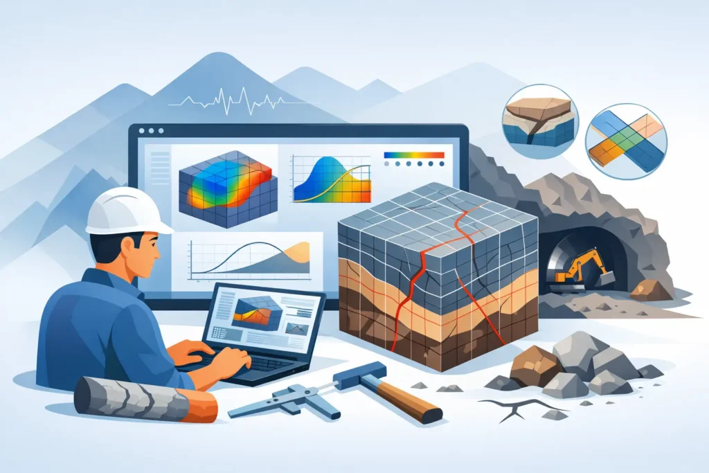
A tunnel face can look competent until mapped joints, groundwater and an unfavourable stress field tell a different story. A useful guide to rock mechanics software therefore starts with the engineering decision, not with a catalogue of numerical methods. The right tool should help the engineer make assumptions visible, test credible alternatives and communicate the implications for excavation, support or sequencing.
For rock engineers, software is rarely the analysis in itself. It is part of a chain that begins with geological interpretation and site investigation, continues through a defensible model, and ends with drawings, specifications, observational methods or risk controls. The quality of each link matters.
Start with the question the model must answer
Rock mechanics software is often chosen too early, before the intended output has been defined. A preliminary excavation assessment may need a quick kinematic check of wedges and planar failure. A cavern under high in-situ stress may require staged excavation modelling, stress redistribution and support interaction. A slope above infrastructure may need block geometry, groundwater scenarios and sensitivity to discontinuity persistence.
These are different problems. They do not become better defined merely because they are placed in a detailed three-dimensional model.
Before selecting software, write down the decision to be supported. Is the purpose to screen alternatives, establish a support class, estimate deformation, assess a local stability mechanism, or provide input to contractual design documentation? Then identify the governing outputs: factor of safety, displacement, support force, stress concentration, plastic zone extent, water pressure, or a clear graphical representation of a potential failure mechanism.
This discipline also prevents false precision. If joint orientation, persistence or rock mass properties are uncertain, a result with several decimal places can imply confidence that the investigation does not support. Sensitivity studies are usually more valuable than a single refined run.
What this guide to rock mechanics software covers
The most practical way to assess a program is by the class of analysis it performs and the assumptions it requires. In many projects, several focused tools are preferable to one large model used for every question.
Kinematic and discontinuity analysis
For structurally controlled failures, stereographic projection and block or wedge analysis remain essential. These tools allow the engineer to relate discontinuity orientation, excavation geometry and friction assumptions directly to possible sliding, toppling or wedge release.
Their strength is transparency. Inputs can usually be reviewed against face mapping or borehole data, and the resulting failure geometry is easy to discuss with design colleagues and site staff. Their limitation is equally clear: they cannot represent every aspect of deformable rock mass behaviour, stress-induced damage or complex support interaction. They should be used where the mechanism is genuinely structure-controlled, not as a default for all rock slopes and tunnels.
Empirical rock mass assessment
Rock mass classification and empirical support methods can be efficient at early stages and remain useful during construction. They organise observations of rock quality, joint conditions, groundwater and stress effects into a repeatable framework for comparing reaches of tunnel or excavation.
Software can make this process quicker and more consistent, particularly when input is recorded in the field. However, classifications are not a substitute for geological judgement. A numerical rating does not remove the need to consider fault zones, squeezing ground, spalling potential, anisotropy, water inflow or the consequences of a local block fall. The selected method must also be appropriate to the excavation type and the evidence on which its correlations were established.
Continuum numerical modelling
Finite-element and finite-difference tools are commonly used where stress redistribution, deformation and staged construction govern performance. Typical applications include tunnel convergence, pillar response, cavern stability, cut-and-cover interfaces, rock slope deformation and interaction between support and ground.
A continuum model treats the rock mass as a material with constitutive behaviour. This can be very effective for large-scale response, but it requires careful judgement when discrete joints dominate. Material models, boundary conditions, initial stress state, groundwater representation and excavation sequence can all materially affect the result. A visually convincing contour plot is not evidence that these choices are correct.
For this class of work, inspect whether the software supports the construction stages, support elements and groundwater conditions relevant to the project. Just as importantly, check how easily assumptions, units, boundary conditions and outputs can be reviewed by another engineer.
Discontinuum and hybrid modelling
When block movement, joint opening, sliding or separation are central to the problem, discontinuum methods may be more appropriate. They represent rock blocks and contacts explicitly, allowing an analysis to reflect mechanisms that a homogenised continuum model can obscure.
The trade-off is a higher demand for geological input and model definition. Joint sets, spacing, persistence, contact stiffness, shear strength and block geometry need a defensible basis. Hybrid approaches can be valuable where both the broad rock mass response and local discontinuities matter, but they should be justified by the decision at stake. Complexity is worthwhile only when it changes the engineering conclusion.
Judge input handling as carefully as the solver
An analysis is only as reliable as its input. Good rock mechanics software should make it straightforward to enter geological and geotechnical parameters, document their source and revise them as the ground model develops. Clear handling of coordinate systems, conventions for dip and dip direction, units, sign conventions and water pressures is particularly important.
Look for input screens that expose rather than conceal the model. Engineers should be able to see which values were adopted for intact rock strength, deformation modulus, joint friction, cohesion, tensile strength, rock mass classification and support properties. Where parameters are derived from correlations, the basis should be apparent.
This matters during design reviews. A colleague should be able to follow the model without reconstructing it from memory, and a site engineer should be able to understand which observations would trigger a reassessment. Simple, user-friendly input handling is not a cosmetic feature. It reduces avoidable transcription errors and makes peer checking more efficient.
Treat verification and calibration as part of the workflow
No software package removes the need for verification. Start with hand calculations, simple limiting cases or published benchmark examples wherever practical. A wedge analysis can be checked geometrically. A continuum model can be tested against an elastic solution or a simplified support-pressure relationship. If a model cannot reproduce a known simple behaviour, its result for a complicated excavation deserves little confidence.
Calibration should use project evidence where available: convergence monitoring, extensometer readings, deformation surveys, mapping of overbreak, support loads, stress measurements or observed damage. Calibration is not the act of adjusting parameters until the output looks favourable. It is a structured comparison between predicted and observed behaviour, with a record of what has changed and why.
Observational data are especially valuable in tunnelling. They can show whether the assumed ground class, deformation modulus, stress regime or support response is reasonable. They can also reveal that the original model was asking the wrong question.
Choose outputs that support engineering decisions
Results need to be technically meaningful and easy to communicate. For a kinematic assessment, this may mean stereonets, wedge geometry and a concise explanation of assumptions. For a numerical model, it may mean displacement profiles, stress paths, support demand, plastic zones and stage-by-stage plots rather than a large collection of unfiltered contours.
Reporting should state the model purpose, geometry, data sources, parameter ranges, material laws, groundwater assumptions, boundary conditions and excavation sequence. It should distinguish calculated output from engineering interpretation. For example, a computed zone of yielding may indicate potential damage or stress relief, but it does not automatically define the final support requirement.
The ability to create clear graphics and text-based outputs is particularly useful when communicating between design office, site and client. A result that can be understood on a desktop computer, tablet or phone is often more useful during active works than a model locked into a specialist workstation.
Consider platform fit and long-term use
Engineering teams increasingly work across office, site and home locations. For professionals using macOS, iPad and iPhone, platform support is more than a procurement detail. It affects whether field observations can be checked promptly, whether calculations can be reviewed away from the desk, and whether project files remain accessible without a parallel Windows workflow.
Psicons AB develops specialised geotechnical and tunnelling applications for the Apple ecosystem with this practical use in mind. The relevant test for any application is not the length of its feature list, but whether it supports reliable problem set-up, calculation and result interpretation in the work engineers actually do.
Also consider file longevity, export formats, version control, licensing, technical documentation and the availability of support from people who understand ground engineering. A low initial cost can become expensive if inputs are difficult to audit or results cannot be reproduced later.
Use software to make judgement easier to audit
The best rock mechanics software does not replace geological understanding or engineering responsibility. It gives that judgement a disciplined structure: stated assumptions, repeatable calculations, sensitivity to uncertainty and outputs that others can examine.
Choose the simplest method that can represent the governing mechanism, then increase model complexity only when the project evidence and decision justify it. That approach produces analyses that are easier to check, easier to explain and more useful when the ground behaves differently from the first interpretation.