
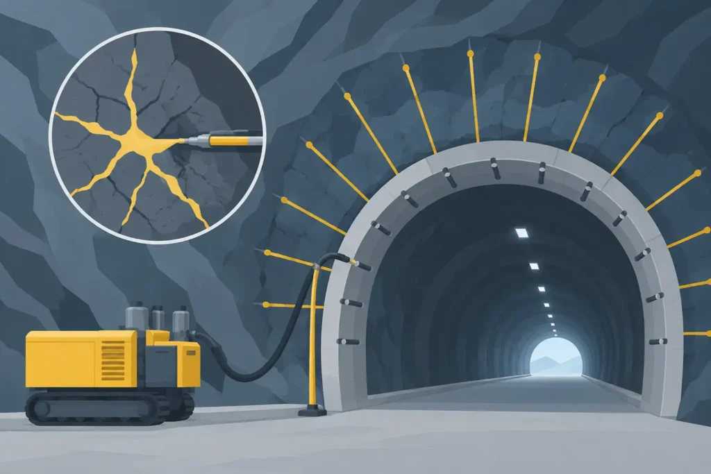
A grouting fan that looks regular on a tunnel drawing can still leave an irregular hydraulic barrier in the rock. The difference is rarely the drilling pattern alone. To design rock grouting spread properly, the engineer must relate the planned holes to the fracture network, the grout mix, the pressure limits and the required hydraulic performance.
For pre-excavation grouting, “spread” is often used loosely. It may mean the radial extent of grout away from a borehole, the effective influence radius used to set hole spacing, or the total treated zone around the excavation. These are related, but they are not interchangeable. Treating a calculated spread as a guaranteed radius is one of the quickest ways to create false confidence in a design.
What rock grouting spread means in practice
In a tunnel heading, grout is injected through packered stages in holes drilled ahead of the face. The objective is normally to reduce water inflow and improve local ground conditions before excavation enters the treated volume. A fan must therefore provide continuity around the planned contour and enough longitudinal overlap with the next fan.
The effective spread is the distance over which grout penetrates the connected, groutable fractures at a useful residual aperture. It is controlled by discontinuity geometry and connectivity, not by the borehole length. A hole can accept a large grout take while contributing little useful sealing if grout follows one persistent, favourably oriented feature away from the zone that needs treatment.
For design purposes, spread is best treated as an engineering hypothesis. It is established from geological information, previous grouting records, trials and verification results, then revised as excavation progresses. The result is a defensible basis for hole spacing and fan geometry, rather than a fixed number applied to every rock mass.
Start with the required treated envelope
The design should begin outside the grout holes. Define the tunnel profile, the required thickness of the treated zone beyond the contour, the round length and the allowable inflow criterion. These decisions establish the volume that must be treated and the consequences of an untreated window.
A typical pre-grouting arrangement comprises a ring or partial ring of holes drilled at an outward angle from the tunnel axis. The holes are often extended beyond the planned face to provide overlap with the subsequent fan. The required overlap is not merely a drafting convention. It protects against deviations in drilling, local variation in spread and the possibility that the next round encounters a more permeable fracture set.
The necessary envelope depends on the project. A pressure tunnel beneath sensitive ground, a rail tunnel with strict environmental limits and a hard-rock cavern with limited water pressure do not justify the same design target. Greater water pressure, sensitive receptors and uncertain geology generally call for a more conservative treated thickness, closer spacing or both.
Use the geological model as a design input
Rock mass classification alone is insufficient for grouting design. The model must describe the discontinuities that carry water: their orientations, spacing, persistence, roughness, infilling, aperture and connectivity. Fault zones, sheared contacts, dykes and stress-relief fractures should be considered separately from the background jointing.
Orientation matters because a fan intersects some fracture sets well and others poorly. Holes drilled symmetrically around a profile may give asymmetric treatment when the dominant joints dip strongly or strike parallel to the tunnel. In such conditions, adjust fan angles, add targeted holes or reduce spacing in the vulnerable sector rather than assuming an even radial spread.
Probe drilling, water-pressure testing and drilling observations provide valuable evidence. Sudden changes in penetration rate, water losses, returns and grout takes can identify zones that deserve a different design response. They should not be treated as isolated production records; they are observations of the rock mass ahead.
Estimating grout penetration without false precision
Grout movement through a single ideal fracture can be described with flow relationships in which aperture has a dominant influence. In simplified form, transmissivity rises approximately with the cube of fracture aperture. A small difference in aperture can therefore produce a large difference in groutability and water conductivity.
Real rock is more complicated. Aperture varies along the fracture, grout viscosity changes with time, fractures intersect, and filtration may occur at constrictions. Cement particles can bridge narrow apertures even where water previously passed through. Pressure can open compliant fractures, while excessive pressure can create hydraulic jacking or drive grout beyond the intended area.
For these reasons, a calculated penetration length is useful as a sensitivity check, not as a precise forecast. It helps the engineer compare mixes, injection times, pressure ranges and assumed apertures. It does not remove the need for field calibration.
A practical approach is to define a design spread range. The lower bound should support the selected hole spacing in poor but plausible groutability conditions. The upper bound can indicate the risk of long preferential flow paths, unwanted losses or interaction with neighbouring works. The adopted spacing should reflect the lower credible effective spread, while acceptance criteria and monitoring manage the uncertainty.
Grout mix and pressure belong to the same decision
A finer grout can enter narrower fractures, but it may have different cost, bleeding behaviour, setting characteristics and sensitivity to water conditions. A coarser cement grout may be entirely suitable in open-jointed rock yet ineffective in tight fracture networks. The selected mix must match the expected aperture distribution and the required permeability reduction.
Injection pressure must be sufficient to move grout through the connected fractures, but it must remain compatible with the rock mass, overburden and nearby structures. Pressure limits are commonly varied by depth and geological zone. A single maximum pressure for every stage is simple to specify, but it can be a poor representation of actual risk.
Pressure, volume, flow rate and grout mix changes should be logged by stage. These records show whether injection is reaching a distributed fracture network or following isolated conductive features. They also support rapid adjustment of the fan when results depart from the design assumptions.
Convert spread into hole spacing and fan overlap
If the adopted effective spread from each hole is represented by a radius, spacing must allow the treated zones to overlap. In a uniform conceptual model, centre-to-centre spacing should be appreciably less than twice the assumed radius. In real rock, however, neither penetration nor fracture connectivity is circular. The design margin must account for drilling deviation, anisotropy and variable groutability.
This is why nominally generous spacing can fail at the tunnel shoulder or invert. These areas may be harder to drill accurately, may contain stress-relief fracturing, and can be poorly covered by an otherwise regular fan. The contour should be reviewed sector by sector, not only as a total number of holes.
Longitudinal overlap is equally important. If the holes extend only to the next planned face, the end of one treatment zone may not connect reliably with the next. Overlap between fans creates continuity along the tunnel axis and provides tolerance for shorter-than-planned penetration. The appropriate length depends on round length, hole deviation, fan angle, ground variability and the consequence of leakage.
A design drawing should therefore state more than hole count and length. It should identify the intended treated envelope, hole positions and orientations, stage lengths, pressure limits, grout types, overlap, anticipated variation by geological domain and the trigger for supplementary holes.
Verification is part of the design rock grouting spread
Verification determines whether the assumed spread produced the intended hydraulic result. Control holes, probe holes, water-pressure tests, measured inflow and the response during excavation all contribute evidence. No single measure is decisive in every rock mass.
Control holes should be placed where the design is most likely to be weak: between primary holes, near structural features and in sectors with unfavourable fracture orientation. A control hole that shows high water loss or significant grout acceptance may indicate an untreated connection, but its interpretation must consider the test method, test pressure and local geology.
Observed grout take is also ambiguous. Low take can mean the rock is tight, the fractures are already filled, the stage is poorly connected or the grout has filtered near the borehole. High take can indicate successful penetration, but it can also signal a major open feature. Combining stage records with water testing and face mapping provides a much more reliable interpretation.
Where results show incomplete treatment, the response may be supplementary holes, altered spacing, a finer grout, shorter stages, revised pressure control or a changed fan geometry. Adding cement indiscriminately is not a design correction. The corrective measure should address the reason the original assumption failed.
Make the calculation workflow traceable
For design work, the value of a calculation tool lies in making assumptions visible. Inputs should be easy to inspect: tunnel geometry, hole geometry, assumed spread, overlap, grout properties, pressure criteria and geological domain. The graphical output should show the treated envelope relative to the planned excavation, while a clear text output records the basis for review and revision.
This is particularly useful when the work moves between office, tunnel and site meeting. A calculation that can be checked on a Mac and reviewed on an iPad is more likely to remain connected to actual drilling and grouting records. Psicons AB develops focused engineering tools around this practical need for straightforward input handling and results that are easy to follow in detail.
A good grouting design is not the one with the most conservative fan on paper. It is the one that states its assumptions clearly, tests them against the rock ahead and gives the site team a practical route to adjust before water finds the gaps.
