
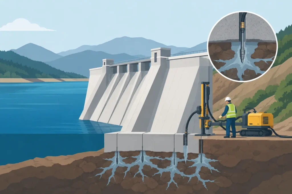
A dam foundation grouting case study is most useful when it shows the chain of engineering decisions, not simply the final grout take. For dam owners and designers, the question is rarely whether grout can be injected into a foundation. The question is whether the selected programme reduces seepage and uplift risk without creating hydraulic fractures, displacing fines, or giving a false impression of treatment continuity.
The representative case below illustrates how a foundation grouting programme can be developed from observed seepage behaviour to a verified curtain design. The values are deliberately simplified, but the reasoning reflects the issues encountered in fractured rock foundations beneath concrete and embankment dams.
Dam foundation grouting case study: the engineering problem
The structure in this case is a mature concrete gravity dam founded on moderately weathered crystalline rock. Historic instrumentation showed that total drainage flow was stable for many years, but piezometers near the left abutment began recording a gradual rise in uplift pressure during high reservoir levels. Surface inspections also identified localised wet areas downstream of the abutment contact.
The initial temptation in such a situation is to specify a deeper and tighter grout curtain. That may be justified, but it is not a diagnosis. Increased pressure can result from an open joint set, deterioration at the concrete-rock contact, a bypass around an existing curtain, blocked drains, changes in reservoir operation, or a combination of these mechanisms. Each demands a different response.
The investigation therefore began by reviewing construction records, previous water pressure tests, grout logs, drainage measurements and piezometric response against reservoir level. These records were supplemented by inclined core holes through the suspected abutment zone. Core recovery, fracture frequency, joint infill and weathering were logged consistently, while water pressure testing was carried out in short test sections.
The result was not a uniform permeability profile. The upper 8 to 12 metres of rock contained weathered, partly open fractures with variable response. Below this zone, most test sections showed low permeability, except for a persistent steeply dipping fracture set that intersected the left abutment contact. Several tests also showed pressure-dependent water loss, indicating that test pressure itself was opening existing discontinuities or extending flow paths.
That distinction matters. A high water loss at an unsuitable pressure does not automatically demonstrate a large, naturally open conduit. It may describe the test procedure as much as the rock mass.
Establishing a defensible treatment objective
The treatment objective was defined as a reduction in hydraulic connection between the reservoir and the downstream abutment zone, together with lower uplift pressures at the affected instruments. It was not defined as achieving a particular cement consumption per metre.
A target based only on grout take is unreliable. Low take may mean that rock is tight, that grout has set prematurely, or that the borehole is poorly connected to the fractures of concern. High take may indicate successful filling, but it can also signal uncontrolled travel along a major discontinuity. The required evidence comes from several observations considered together.
The design team selected a primary, secondary and tertiary hole sequence, with hole spacing progressively reduced where the geological and hydraulic evidence supported it. The curtain was extended locally beneath the abutment rather than uniformly across the whole dam. This focused the work on the identified seepage pathway and limited unnecessary drilling in competent foundation rock.
Grout mixes were specified as a family rather than one fixed recipe. A stable cement-based suspension was used initially in wider fractures, followed by finer material where water pressure tests and grout refusal patterns indicated tighter apertures. The appropriate material depends on aperture distribution, groundwater chemistry, temperature, delivery equipment and the intended penetration distance. A finer grout is not automatically better if it cannot be mixed, pumped and controlled consistently on site.
Pressure is a design variable, not a production setting
The permissible pressure was set by depth, overburden and local rock conditions, then adjusted through a trial section. Near the concrete-rock interface and shallow weathered rock, low pressures were used to reduce the chance of lifting, hydrofracturing or driving grout into unwanted paths. At greater depth in sound rock, pressure could be increased within defined limits.
The trial section was particularly valuable because it tested the real interaction between mix, pressure, stage length and rock mass. Several primary holes accepted unexpectedly large volumes at shallow depth. Instead of simply continuing at the same pressure, the crew reduced stage length, changed the sequence of adjacent holes and monitored nearby observation holes. Subsequent secondary holes showed reduced takes, suggesting that the treatment was progressively intercepting the connected fracture network rather than merely filling isolated pockets.
This is where disciplined digital records make a material difference. For each stage, the engineer needs depth, water test result, mix, pressure history, flow rate, volume, refusal criteria, interruptions and observations of returns. A plotted pressure-volume-time record is often more revealing than a single final volume. It can show sudden loss of confinement, gradual penetration, early refusal or a change in behaviour after a mix adjustment.
Reading the grout records in context
In the representative programme, primary holes averaged moderate takes but had a wide spread. A small number of stages adjacent to the abutment contact took several times the average volume. Secondary holes generally accepted less grout, while tertiary holes were mainly at refusal after limited injection.
That pattern was encouraging, but it was not accepted as proof on its own. The key question was whether the declining take reflected improved curtain continuity or whether it resulted from poor borehole communication. Verification holes were therefore positioned to cross the inferred seepage zone, rather than being placed only where favourable results were expected.
Water pressure tests in verification holes indicated a substantial reduction in water loss within the treated upper rock zone. More importantly, piezometric monitoring through a subsequent reservoir cycle showed a lower and slower uplift response near the left abutment. Drainage flow did not fall uniformly across the dam, which was reasonable because the work targeted a local pathway rather than the entire foundation.
The differing responses are a useful reminder that drainage flow, uplift pressure and water pressure test results measure related but different aspects of foundation behaviour. A lower water pressure test value may indicate reduced local transmissivity. A lower piezometric head indicates changed hydraulic conditions at an instrument. Neither should be used carelessly as a substitute for the other.
What the case changes in practice
The principal lesson from this dam foundation grouting case study is that a grout curtain should be treated as an engineered hydraulic system, not as a line of holes completed to a drawing. Geology, water pressure response, construction sequence and monitoring data must all influence the programme while work is in progress.
There are trade-offs. Closely spaced holes and fine grouts can improve the probability of intercepting narrow fractures, but they increase drilling time, cost and the potential for excessive treatment in already tight rock. Higher injection pressures may improve penetration at depth, yet they can also create fractures or connect undesirable pathways. A conservative programme can be safer near sensitive contacts, but may leave important defects untreated if it is not supported by appropriate investigation.
For engineers managing the works, the practical requirement is traceability. The design assumptions should be visible, field changes should be recorded with reasons, and verification criteria should be agreed before production grouting begins. Software used for calculation, logging and graphical review should support this judgement rather than obscure it behind excessive input complexity.
Psicons AB develops geotechnical tools around that principle: straightforward input handling, calculations that remain easy to follow in detail, and outputs that help engineers interpret the ground rather than merely process data.
A well-executed grouting programme leaves more than lower permeability values. It leaves a record that allows the next engineer to understand what was found, why treatment changed, and how the foundation response justified confidence in the result.
